Math Is Fun Forum
You are not logged in.
- Topics: Active | Unanswered
#151 2018-06-09 12:40:35
- Monox D. I-Fly
- Member

- From: Indonesia
- Registered: 2015-12-02
- Posts: 2,000
Re: Miscellany
(The name may be somewhat of a misnomer - game theory generally does not share the fun or frivolity associated with games.)
So that's why I never enjoy learning about game theory.
Actually I never watch Star Wars and not interested in it anyway, but I choose a Yoda card as my avatar in honor of our great friend bobbym who has passed away.
May his adventurous soul rest in peace at heaven.
Offline
#152 2018-06-09 17:32:45
- Jai Ganesh
- Administrator

- Registered: 2005-06-28
- Posts: 53,831
Re: Miscellany
ganesh wrote:(The name may be somewhat of a misnomer - game theory generally does not share the fun or frivolity associated with games.)
So that's why I never enjoy learning about game theory.
![]()
![]()
135) Chromium
Chromium (Cr), chemical element of Group 6 (VIb) of the periodic table, a hard, steel-gray metal that takes a high polish and is used in alloys to increase strength and corrosion resistance. Chromium was discovered (1797) by the French chemist Nicolas-Louis Vauquelin and isolated as the metal a year later; it was named for its multicoloured compounds. The green colour of emerald, serpentine, and chrome mica and the red colour of ruby are due to small amounts of chromium. The name of the element chromium (from Greek chrōmos, “colour”) connotes the pronounced and varied colorations of chromium compounds.
Occurrence, Uses, And Properties
Chromium is a relatively abundant element in Earth’s crust; the free metal is never found in nature. Most ores consist of the mineral chromite, the ideal formula of which is FeCr2O4. It is widely dispersed in natural deposits, which are usually contaminated with oxygen, magnesium, aluminum, and silica; their chromium content varies from 42 to 56 percent. One of the chief uses of chromium is in ferrous alloys, for which the pure metal is not required. Accordingly, chromite is often reduced with carbon in a furnace, producing the alloy ferrochromium, which contains iron and chromium in an atom ratio of approximately 1 to 2.
To obtain pure chromium, chromite is first treated with molten alkali and oxygen, converting all of the chromium to the alkali chromate, and the latter is dissolved in water and eventually precipitated as sodium dichromate, Na2Cr2O7. The dichromate is then reduced with carbon to chromium sesquioxide, Cr2O3, and that oxide in turn is reduced with aluminum to give the chromium metal.
Chromium is added to iron and nickel in the form of ferrochromium to produce alloys specially characterized by their high resistance to corrosion and oxidation. Used in small amounts, chromium hardens steel. Stainless steels are alloys of chromium and iron in which the chromium content varies from 10 to 26 percent. Chromium alloys are used to fabricate such products as oil tubing, automobile trim, and cutlery. Chromite is used as a refractory and as a raw material for the production of chromium chemicals.
The metal is white, hard, lustrous, and brittle and is extremely resistant to ordinary corrosive reagents; this resistance accounts for its extensive use as an electroplated protective coating. At elevated temperatures chromium unites directly with the halogens or with sulfur, silicon, boron, nitrogen, carbon, or oxygen. (For additional treatment of chromium metal and its production, see chromium processing.)
Natural chromium consists of a mixture of four stable isotopes: chromium-52 (83.76 percent), chromium-53 (9.55 percent), chromium-50 (4.31 percent), and chromium-54 (2.38 percent). The metal is paramagnetic (weakly attracted to a magnet). It exists in two forms: body-centred cubic (alpha) and hexagonal close-packed (beta). At room temperature, chromium slowly dissolves in hydrochloric and dilute sulfuric acids. Certain oxidizing agents produce a thin unreactive oxide layer on the metal, rendering it passive also to dilute mineral acids, such as sulfuric, nitric, or cold aqua regia. At ordinary temperatures the metal shows no reaction to seawater or to wet or dry air.
Top producers of chromium include South Africa, India, Kazakhstan, and Turkey.
Principal Compounds
The most common oxidation states of chromium are +6, +3, and +2. A few stable compounds of the +5, +4, and +1 states, however, are known.
In the +6 oxidation state, the most important species formed by chromium are the chromate, and dichromate, ions. These ions form the basis for a series of industrially important salts. Among them are sodium chromate, Na2CrO4, and sodium dichromate, Na2Cr2O7, which are used in leather tanning, in metal surface treatment, and as catalysts in various industrial processes.
Chromium forms several commercially valuable oxygen compounds, the most important of which is chromium oxide, commonly called chromium trioxide or chromic acid, CrO3, in which chromium is in the +6 oxidation state. An orange-red crystalline solid, chromic acid liquefies gradually when exposed to moist air. It is usually produced by treatment of sodium dichromate with sulfuric acid. Chromic acid is used chiefly for chromium plating but is also employed as a colorant in ceramics. It is a powerful oxidant and may react violently with some organic materials, but such solutions are often utilized by controlled oxidations in organic synthesis.
Another significant oxygen compound is chromium oxide, also known as chromium sesquioxide or chromic oxide, Cr2O3, in which chromium is in the +3 oxidation state. It is prepared by calcining sodium dichromate in the presence of carbon or sulfur. Chromium oxide is a green powder and is employed extensively as a pigment; its hydrate form, known as Guignet’s green, is used when chemical and heat resistance are required.

It appears to me that if one wants to make progress in mathematics, one should study the masters and not the pupils. - Niels Henrik Abel.
Nothing is better than reading and gaining more and more knowledge - Stephen William Hawking.
Offline
#153 2018-06-11 01:14:57
- Jai Ganesh
- Administrator
- Registered: 2005-06-28
- Posts: 53,831
Re: Miscellany
136) Polytetrafluoroethylene (PTFE)
Polytetrafluoroethylene (PTFE), a strong, tough, waxy, nonflammable synthetic resin produced by the polymerization of tetrafluoroethylene. Known by such trademarks as Teflon, Fluon, Hostaflon, and Polyflon, PTFE is distinguished by its slippery surface, high melting point, and resistance to attack by almost all chemicals. These properties have made it familiar to consumers as the coating on nonstick cookware; it is also fabricated into industrial products, including bearings, pipe liners, and parts for valves and pumps.
PTFE was discovered serendipitously in 1938 by Roy Plunkett, an American chemist for E.I. du Pont de Nemours & Company (now DuPont Company), who found that a tank of gaseous tetrafluoroethylene refrigerant had polymerized to a white powder. During World War II it was applied as a corrosion-resistant coating to protect metal equipment used in the handling of radioactive material for the Manhattan Project. For more than a decade after the war, PTFE saw little commercial use, owing to difficulties encountered in devising methods for processing the slippery, high-melting material. DuPont released its trademarked Teflon-coated nonstick cookware in 1960.
Tetrafluoroethylene (C2F4), a colourless, odourless gas, is made by heating chlorodifluoromethane (CHClF2) in the range of 600–700 °C (1,100–1,300 °F). Chlorodifluoromethane in turn is obtained by reacting hydrogen fluoride (HF) with chloroform (CHCl3). Tetrafluoroethylene monomers (small, single-unit molecules) are suspended or emulsified in water and then polymerized (linked into giant, multiple-unit molecules) under high pressure in the presence of free-radical initiators. The polymer consists of a chain of carbon atoms with two fluorine atoms bonded to each carbon.
The fluorine atoms surround the carbon chain like a protective sheath, creating a chemically inert and relatively dense molecule with very strong carbon-fluorine bonds. The polymer is inert to most chemicals, does not melt below 327 °C (620 °F), and has the lowest coefficient of friction of any known solid. These properties allow it to be used for bushings and bearings that require no lubricant, as liners for equipment used in the storage and transportation of strong acids and organic solvents, as electrical insulation under high-temperature conditions, and in its familiar application as a cooking surface that does not require the use of fats or oils.
Fabrication of PTFE products is difficult because the material does not flow readily even above its melting point. Molded parts can be made by compressing and heating fine powders mixed with volatile lubricants. Metallic surfaces can be sprayed or dipped with aqueous dispersions of PTFE particles to form a permanent coating. Dispersions of PTFE can also be spun into fibres.

It appears to me that if one wants to make progress in mathematics, one should study the masters and not the pupils. - Niels Henrik Abel.
Nothing is better than reading and gaining more and more knowledge - Stephen William Hawking.
Offline
#154 2018-06-12 22:32:13
- Jai Ganesh
- Administrator
- Registered: 2005-06-28
- Posts: 53,831
Re: Miscellany
137) Bulldozer
Bulldozer, also called Dozer, powerful machine for pushing earth or rocks, used in road building, farming, construction, and wrecking; it consists of a heavy, broad steel blade or plate mounted on the front of a tractor. Sometimes it uses a four-wheel-drive tractor, but usually a track or crawler type, mounted on continuous metal treads, is employed. The blade may be lifted and forced down by hydraulic rams. For digging, the blade is held below surface level; for transporting, it is held at the surface level; and for spreading, it is held above the surface level, as the tractor moves forward.
Bulldozers are used for shallow digging and ditching; short-range transportation of material; spreading soil dumped from trucks; rough grading; removing trees, stumps, and boulders; and cleaning and leveling around loading equipment. A bulldozer alone can do many types of excavation, and it is useful in combination with other machinery in most excavation work.
It appears to me that if one wants to make progress in mathematics, one should study the masters and not the pupils. - Niels Henrik Abel.
Nothing is better than reading and gaining more and more knowledge - Stephen William Hawking.
Offline
#155 2018-06-15 01:13:27
- Jai Ganesh
- Administrator
- Registered: 2005-06-28
- Posts: 53,831
Re: Miscellany
138) Kaleidoscope
Kaleidoscope, optical device consisting of mirrors that reflect images of bits of coloured glass in a symmetrical geometric design through a viewer. The design may be changed endlessly by rotating the section containing the loose fragments. The name is derived from the Greek words kalos (“beautiful”), eïdos (“form”), and skopeïn (“to view”).Kaleidoscope, optical device consisting of mirrors that reflect images of bits of coloured glass in a symmetrical geometric design through a viewer. The design may be changed endlessly by rotating the section containing the loose fragments. The name is derived from the Greek words kalos (“beautiful”), eïdos (“form”), and skopeïn (“to view”).
The kaleidoscope was invented by Sir David Brewster about 1816 and patented in 1817. Sold usually as a toy, the kaleidoscope also has value for the pattern designer.
The kaleidoscope illustrates the image-forming properties of combined, inclined mirrors. If an object is placed between two mirrors inclined at right angles, an image is formed in each mirror. Each of these mirror images is in turn reflected in the other mirror, forming the appearance of four symmetrically placed objects. If the mirrors are inclined at 60°, a hexagonally symmetrical pattern results from one object producing six regularly placed images.
A simple kaleidoscope consists of two thin, wedge-shaped mirror strips touching along a common edge or of a single sheet of bright aluminum bent to an angle of 60° or 45°. The mirrors are enclosed in a tube with a viewing eyehole at one end. At the other end is a thin, flat box that can be rotated; it is made from two glass disks, the outer one ground to act as a diffusing screen. In this box are pieces of coloured glass, tinsel, or beads. When the box is turned or tapped, the objects inside tumble into an arbitrary grouping, and when the diffusing screen is illuminated, the sixfold or eightfold multiplication creates a striking symmetrical pattern. The number of combinations and patterns is effectively without limit.
Some kaleidoscopes dispense with the object box and use a lens to throw images of distant objects on the mirrors, an eyepiece at the viewing eyehole then being an advantage.

It appears to me that if one wants to make progress in mathematics, one should study the masters and not the pupils. - Niels Henrik Abel.
Nothing is better than reading and gaining more and more knowledge - Stephen William Hawking.
Offline
#156 2018-06-17 00:11:17
- Jai Ganesh
- Administrator
- Registered: 2005-06-28
- Posts: 53,831
Re: Miscellany
139) Dead Sea
Dead Sea, Arabic Al-Baḥr Al-Mayyit (“Sea of Death”), Hebrew Yam HaMelaẖ (“Salt Sea”), also called Salt Sea, landlocked salt lake between Israel and Jordan in southwestern Asia. Its eastern shore belongs to Jordan, and the southern half of its western shore belongs to Israel. The northern half of the western shore lies within the Palestinian West Bank and has been under Israeli occupation since the 1967 Arab-Israeli war. The Jordan River, from which the Dead Sea receives nearly all its water, flows from the north into the lake.
The Dead Sea has the lowest elevation and is the lowest body of water on the surface of Earth. For several decades in the mid-20th century the standard value given for the surface level of the lake was some 1,300 feet (400 metres) below sea level. Beginning in the 1960s, however, Israel and Jordan began diverting much of the Jordan River’s flow and increased the use of the lake’s water itself for commercial purposes. The result of those activities was a precipitous drop in the Dead Sea’s water level. By the mid-2010s measurement of the lake level was more than 100 feet (some 30 metres) below the mid-20th-century figure—i.e., about 1,410 feet (430 metres) below sea level—but the lake continued to drop by about 3 feet (1 metre) annually.
Physical Features
Physiography and geology
The Dead Sea is situated between the hills of Judaea to the west and the Transjordanian plateaus to the east. Before the water level began dropping, the lake was some 50 miles (80 km) long, attained a maximum width of 11 miles (18 km), and had a surface area of about 394 square miles (1,020 square km). The peninsula of Al-Lisān (Arabic: “The Tongue”) divided the lake on its eastern side into two unequal basins: the northern basin encompassed about three-fourths of the lake’s total surface area and reached a depth of 1,300 feet (400 metres), and the southern basin was smaller and considerably shallower, less than 10 feet (3 metres) deep on average. During biblical times and until the 8th century CE, only the area around the northern basin was inhabited, and the lake was slightly lower than its present-day level. It rose to its highest level, 1,275 feet (389 metres) below sea level, in 1896 but receded again after 1935, stabilizing at about 1,300 feet (400 metres) below sea level for several decades.
The drop in the lake level in the late 20th and early 21st centuries changed the physical appearance of the Dead Sea. Most noticeably, the peninsula of Al-Lisān gradually extended eastward, until the lake’s northern and southern basins became separated by a strip of dry land. In addition, the southern basin was eventually subdivided into dozens of large evaporation pools (for the extraction of salt), so by the 21st century it had essentially ceased to be a natural body of water. The northern basin—effectively now the actual Dead Sea—largely retained its overall dimensions despite its great loss of water, mainly because its shoreline plunged downward so steeply from the surrounding landscape.
The Dead Sea region occupies part of a graben (a downfaulted block of Earth’s crust) between transform faults along a tectonic plate boundary that runs northward from the Red Sea–Gulf of Suez spreading centre to a convergent plate boundary in the Taurus Mountains of southern Turkey. The eastern fault, along the edge of the Moab Plateau, is more readily visible from the lake than is the western fault, which marks the gentler Judaean upfold.
In the Jurassic and Cretaceous periods (about 201 million to 66 million years ago), before the creation of the graben, an extended Mediterranean Sea covered Syria and Palestine. During the Miocene Epoch (23 million to 5.3 million years ago), as the Arabian Plate collided with the Eurasian Plate to the north, upheaval of the seabed produced the upfolded structures of the Transjordanian highlands and the central range of Palestine, causing the fractures that allowed the Dead Sea graben to drop. At that time the Dead Sea was probably about the size that it is today. During the Pleistocene Epoch (2,588,000 to 11,700 years ago), it rose to an elevation of about 700 feet (200 metres) above its modern level, forming a vast inland sea that stretched some 200 miles (320 km) from the H̱ula Valley area in the north to 40 miles (64 km) beyond its present southern limits. The Dead Sea did not spill over into the Gulf of Aqaba because it was blocked by a 100-foot (30-metre) rise in the highest part of Wadi Al-ʿArabah, a seasonal watercourse that flows in a valley to the east of the central Negev highlands.
Beginning about 2.5 million years ago, heavy streamflow into the lake deposited thick sediments of shale, clay, sandstone, rock salt, and gypsum. Later, strata of clay, marl, soft chalk, and gypsum were dropped onto layers of sand and gravel. Because the water in the lake evaporated faster than it was replenished by precipitation during the past 10,000 years, the lake gradually shrank to its present form. In so doing, it exposed deposits that now cover the Dead Sea valley to thicknesses of between about 1 and 4 miles (1.6 and 6.4 km).
The Al-Lisān region and Mount Sedom (historically Mount Sodom) resulted from movements of Earth’s crust. Mount Sedom’s steep cliffs rise up from the southwestern shore. Al-Lisān is formed of strata of clay, marl, soft chalk, and gypsum interbedded with sand and gravel. Both Al-Lisān and beds made of similar material on the western side of the Dead Sea valley dip to the east. It is assumed that the uplifting of Mount Sedom and Al-Lisān formed a southern escarpment for the Dead Sea. Later the sea broke through the western half of that escarpment to flood what is now the shallow southern remnant of the Dead Sea.
Another consequence resulting from the Dead Sea’s lower water level has been the appearance of sinkholes, especially in the southwestern part of the region. As the water in the lake dropped, it became possible for groundwater to rise up and dissolve large subterranean caverns in the overlying salt layer until the surface finally collapses. Several hundred sinkholes have formed, some of them in areas popular with tourists.
Climate and hydrology
The Dead Sea lies in a desert. Rainfall is scanty and irregular. Al-Lisān averages about 2.5 inches (65 mm) of rain a year, the industrial site of Sedom (near historical Sodom) only about 2 inches (50 mm). Because of the lake’s extremely low elevation and sheltered location, winter temperatures are mild, averaging 63 °F (17 °C) in January at the southern end at Sedom and 58 °F (14 °C) at the northern end; freezing temperatures do not occur. Summer is oppressively hot, averaging 93 °F (34 °C) in August at Sedom, with a recorded maximum of 124 °F (51 °C). Evaporation of the lake’s waters—estimated at about 55 inches (1,400 mm) per year—often creates a thick mist above the lake. On the rivers the atmospheric humidity varies from 45 percent in May to 62 percent in October. Lake and land breezes, which are relatively common, blow off the lake in all directions in the daytime and then reverse direction to blow toward the centre of the lake at night.
The inflow from the Jordan River, whose high waters occur in winter and spring, once averaged some 45.5 billion cubic feet (1.3 billion cubic metres) per year. However, the subsequent diversions of the Jordan’s waters reduced the river’s flow to a small fraction of the previous amount and became the principal cause for the drop in the Dead Sea’s water level. Four modest streams descend to the lake from Jordan to the east through deep gorges: the wadis (intermittent streams) Al-ʿUẓaymī, Zarqāʾ Māʿīn, Al-Mawjib, and Al-Ḥasā. Down numerous other wadis, streams flow spasmodically and briefly from the neighbouring heights as well as from the depression of Wadi Al-ʿArabah. Thermal sulfur springs also feed the rivers. Evaporation in summer and the inflow of water, especially in winter and spring, once caused noticeable seasonal variations of 12 to 24 inches (30 to 60 cm) in the level of the lake, but those fluctuations have been overshadowed by the more-dramatic annual drops in the Dead Sea’s surface level.
Salinity
The waters of the Dead Sea are extremely saline, and, generally, the concentration of salt increases toward the lake’s bottom. That phenomenon can create two different masses of water in the lake for extended periods of time. Such a situation existed for some three centuries, lasting until the late 1970s. Down to a depth of about 130 feet (40 metres), the temperature varied from 66 to 98 °F (19 to 37 °C), the salinity was slightly less than 300 parts per thousand, and the water was especially rich in sulfates and bicarbonates. Beneath a zone of transition located at depths between 130 and 330 feet (40 and 100 metres), the water had a uniform temperature of about 72 °F (22 °C) and a higher degree of salinity (approximately 332 parts per thousand); it contained hydrogen sulfide and strong concentrations of magnesium, potassium, chlorine, and bromine. The deep water was saturated with sodium chloride, which precipitated to the bottom. The deep water thus became fossilized (i.e., because it was highly salty and dense, it remained permanently on the bottom).
The dramatic reduction in inflow from the Jordan River that began in the 1960s gradually increased the salinity of the upper-layer waters of the Dead Sea. By the late 1970s that water mass had become more saline (and denser) than the lower layers, but, because it remained warmer than the layers beneath it, it did not sink. By the winter of 1978–79, however, the upper-level layer had become cool and saturated enough to sink, setting off an event known as an overturn (a mixing of the water layers). Since then the trend has been toward restoring the formerly stratified water layers, but with more instances of overturning.
The saline water has a high density that keeps bathers buoyant. The fresh water of the Jordan stays on the surface, and in the spring its muddy colour can be traced as it spreads southward from the point where the river empties into the Dead Sea. The lake’s extreme salinity excludes all forms of life except bacteria. Fish carried in by the Jordan or by smaller streams when in flood die quickly. Apart from the vegetation along the rivers, plant life along the shores is discontinuous and consists mainly of halophytes (plants that grow in salty or alkaline soil).
Human Imprint
The name Dead Sea can be traced at least to the Hellenistic Age (323 to 30 BCE). The Dead Sea figures in biblical accounts dating to the time of Abraham (first of the Hebrew patriarchs) and the destruction of Sodom and Gomorrah (the two cities along the lake, according to the Hebrew Bible, that were destroyed by fire from heaven because of their wickedness). The desolate wilderness beside the lake offered refuge to David (king of ancient Israel) and later to Herod I (the Great; king of Judaea), who at the time of the siege of Jerusalem by the Parthians in 40 BCE barricaded himself in a fortress at Masada, Israel, just west of Al-Lisān. Masada was the scene of a two-year siege that culminated in the mass suicide of its Jewish Zealot defenders and the occupation of the fortress by the Romans in 73 CE. The Jewish sect that left the biblical manuscripts known as the Dead Sea Scrolls took shelter in caves at Qumrān, just northwest of the lake.
The Dead Sea constitutes an enormous salt reserve. Rock salt deposits also occur in Mount Sedom along the southwestern shore. The salt has been exploited on a small scale since antiquity. In 1929 a potash factory was opened near the mouth of the Jordan. Subsidiary installations were later built in the south at Sedom, but the original factory was destroyed during the 1948–49 Arab-Israeli war. A factory producing potash, magnesium, and calcium chloride was opened in Sedom in 1955. Another plant produces bromine and other chemical products. There are also chemical-processing facilities on the Jordanian side of the southern basin. Water for the extensive array of evaporation pools in the south, from which those minerals are extracted, is supplied by artificial canals from the northern basin.
Because of its location on the contested Jordanian-Israeli frontier, navigation on the Dead Sea is negligible. Its shores are nearly deserted, and permanent establishments are rare. Exceptions are the factory at Sedom, a few hotels and spas in the north, and, in the west, a kibbutz (an Israeli agricultural community) in the region of the ʿEn Gedi oasis. Small cultivated plots are also occasionally found on the lakeshore.
Concern mounted quickly over the continued drop in the Dead Sea’s water level, prompting studies and calls for greater conservation of the Jordan River’s water resources. In addition to proposals for reducing the amount of river water diverted by Israel and Jordan, those two countries discussed proposals for canals that would bring additional water to the Dead Sea. One such project, which received approval from both sides in 2015, would involve constructing a canal northward from the Red Sea. The plan, which would include desalinization and hydroelectric plants along the course of the canal, would deliver large quantities of brine (a by-product of the desalinization process) to the lake. However, the project met with skepticism and opposition from environmentalists and others who questioned the potentially harmful effects of mixing water from the two sources.

It appears to me that if one wants to make progress in mathematics, one should study the masters and not the pupils. - Niels Henrik Abel.
Nothing is better than reading and gaining more and more knowledge - Stephen William Hawking.
Offline
#157 2018-06-18 23:04:07
- Jai Ganesh
- Administrator
- Registered: 2005-06-28
- Posts: 53,831
Re: Miscellany
140) Liquid Oxygen
What Is Liquid Oxygen?
Liquid oxygen is oxygen that’s cooled to -183° C (-297°F) at which point it becomes a pale blue liquid. It is one of the physical forms of the element and serves as an efficient means of supplying home oxygen to a variety of patients.
Liquid Oxygen Supply Systems
The liquid oxygen supply system usually consists of a bulk storage unit or reservoir that’s housed in a permanent place in the home and a refillable, portable unit that you can carry around. The reservoir and portable units have a design similar to that of a thermos bottle, consisting of a container inside a container separated by a vacuum. To remain in liquid form, the oxygen must be stored at very cold temperatures inside the thermos-like container. When you’re ready to use the oxygen and you turn it ON, the liquid warms as it leaves the container, changes to gas, and is supplied at room temperature for you to breathe. Depending upon the manufacturer, there are a wide variety of styles and sizes of liquid oxygen systems, each operating under the same principle.
Understanding the Bulk Stationary Storage Unit
Oxygen is often stored as a liquid – although it’s used primarily as a gas – because it’s less bulky and less expensive than storing the equivalent capacity of high-pressure gas. One liter of liquid oxygen is equivalent to approximately 860 liters of gaseous oxygen. A typical bulk storage unit is filled with approximately 40 liters of liquid oxygen. This may last up to 10 days at a flow rate of 2 liters per minute. When you’re at home, you can use the stationary unit as your primary oxygen source. Depending upon your flow rate, your oxygen supply company will routinely refill the stationary storage unit every 1 to 2 weeks.
Understanding the Portable Container
The portable carrying container can be refilled from the large storage unit whenever necessary. When full, the portable unit typically weighs between 6 and 11 pounds and provides approximately 1,025 liters of gaseous oxygen. When you’re at home and out of reach of your stationary unit, you exercise or perform activities outside the home, you can fill the portable system and be free to go wherever you choose. Because oxygen in its liquid state takes up less space and can be stored at much lower pressures than when in its gaseous state, the portable unit carries more oxygen and is much lighter than a standard oxygen gas cylinder.
Is a Liquid Oxygen Supply System for Me?
Choosing an oxygen supply system is one of the most important decisions you will ever make. If you’re having trouble deciding whether a liquid oxygen system is right for you, it’s a good idea to compare the advantages and disadvantages of different systems.
One of the biggest advantages of using liquid oxygen is that it consumes no electricity. This may be ideal for people on fixed incomes who are unable to afford the higher electricity bills that come with using an oxygen concentrator. Portable liquid oxygen tanks are also lighter and take up less space than compressed gas cylinders making them easier to transport. But oxygen in its liquid form can be more expensive than compressed gas. It can’t be stored for long periods of time because it tends to evaporate. Because the main system needs to be refilled on a regular basis by a service technician, you’re subject to scheduling deliveries, which may be inconvenient. Lastly, refilling the portable tank is said to require dexterity and strength which some folks find difficult.
The Bottom Line
The right oxygen supply system is one that meets your needs and suits your lifestyle. Before you make that choice, talk to your primary health care provider about each system’s pros and cons.

It appears to me that if one wants to make progress in mathematics, one should study the masters and not the pupils. - Niels Henrik Abel.
Nothing is better than reading and gaining more and more knowledge - Stephen William Hawking.
Offline
#158 2018-06-19 23:12:33
- Jai Ganesh
- Administrator
- Registered: 2005-06-28
- Posts: 53,831
Re: Miscellany
141) Phenol
Phenol, any of a family of organic compounds characterized by a hydroxyl (−OH) group attached to a carbon atom that is part of an aromatic ring. Besides serving as the generic name for the entire family, the term phenol is also the specific name for its simplest member, monohydroxybenzene (C6H5OH), also known as benzenol, or carbolic acid.
Phenols are similar to alcohols but form stronger hydrogen bonds. Thus, they are more soluble in water than are alcohols and have higher boiling points. Phenols occur either as colourless liquids or white solids at room temperature and may be highly toxic and caustic.
Phenols are widely used in household products and as intermediates for industrial synthesis. For example, phenol itself is used (in low concentrations) as a disinfectant in household cleaners and in mouthwash. Phenol may have been the first surgical antiseptic. In 1865 the British surgeon Joseph Lister used phenol as an antiseptic to sterilize his operating field. With phenol used in this manner, the mortality rate from surgical amputations fell from 45 to 15 percent in Lister’s ward. Phenol is quite toxic, however, and concentrated solutions cause severe but painless burns of the skin and mucous membranes. Less-toxic phenols, such as n-hexylresorcinol, have supplanted phenol itself in cough drops and other antiseptic applications. Butylated hydroxytoluene (BHT) has a much lower toxicity and is a common antioxidant in foods.
In industry, phenol is used as a starting material to make plastics, explosives such as picric acid, and drugs such as aspirin. The common phenol hydroquinone is the component of photographic developer that reduces exposed silver bromide crystals to black metallic silver. Other substituted phenols are used in the dye industry to make intensely coloured azo dyes. Mixtures of phenols (especially the cresols) are used as components in wood preservatives such as creosote.

It appears to me that if one wants to make progress in mathematics, one should study the masters and not the pupils. - Niels Henrik Abel.
Nothing is better than reading and gaining more and more knowledge - Stephen William Hawking.
Offline
#159 2018-06-21 22:09:28
- Jai Ganesh
- Administrator
- Registered: 2005-06-28
- Posts: 53,831
Re: Miscellany
142) Electroplating
Electroplating, process of coating with metal by means of an electric current. Plating metal may be transferred to conductive surfaces (metals) or to nonconductive surfaces (plastics, wood, leather) after the latter have been rendered conductive by such processes as coating with graphite, conductive lacquer, electroless plate, or a vaporized coating.
Figure 1 shows a typical plating tank containing copper sulfate (CuSO4) solution. A dynamo supplies electric current, which is controlled by a rheostat. When the switch is closed, the cathode bar, which holds the work to be plated, is charged negatively. Some of the electrons from the cathode bar transfer to the positively charged copper ions (Cu2+), setting them free as atoms of copper metal. These copper atoms take their place on the cathode surface, copperplating it. Concurrently, as shown in the drawing, the same number of sulfate ions are discharged on the copper anodes, thereby completing the electrical circuit. In so doing, they form a new quantity of copper sulfate that dissolves in the solution and restores it to its original composition. This procedure is typical of nearly all ordinary electroplating processes; the current deposits a given amount of metal on the cathode and the anode dissolves to the same extent, maintaining the solution more or less uniformly. If this balance is perfect and there are no side reactions or losses, a 100 percent cathode efficiency and 100 percent anode efficiency could possibly be realized.
If the metal surface of the cathode is chemically and physically clean, the discharged atoms of copper are deposited within normal interatomic spacing of the atoms of the basis metal and attempt to become an integral part of it. In fact, if the basis metal is copper, the new copper atoms will frequently arrange themselves to continue the crystal structure of the basis metal, the plate becoming more or less indistinguishable from and inseparable from the basis metal.
If suitable solutions of different metals are mixed, it is possible to plate a wide variety of alloys of metals. By this means plated brass can be made more or less indistinguishable from cast brass. It is also possible, however, to deposit alloys or compounds of metals that cannot be produced by melting and casting them together. For example, tin-nickel alloy plate has been used commercially for its hardness and corrosion resistance, which are superior to that of either metal alone. The deposit consists of a tin-nickel compound (Sn-Ni) that cannot be produced in any other way.
Other common alloy plates include bronze and gold, with varying properties, such as different colours or hardnesses. Magnetic alloy plates of such metals as iron, cobalt, and nickel are used for memory drums in computers. Solder plate (Sn-Pb) is used in printed circuit work.
Development Of Electroplating
While some metal coating procedures date back to ancient times, modern electroplating started in 1800 with Alessandro Volta’s discovery of the voltaic pile, or battery, which made noteworthy quantities of direct current electricity available. At about the same time, the battery was employed to deposit lead, copper, and silver. After a nodule of copper had been deposited on a silver cathode, the copper could not be removed. In the same year, zinc, copper, and silver were deposited on themselves and on a variety of basis metals (the metals on which the plating is applied), such as gold and iron.
Electroplating on a commercial scale was begun about 1840–41 and was accelerated by the discovery of cyanide solutions for plating silver, gold, copper, and brass. A cyanide-copper solution, for example, gave adherent deposits of copper directly on iron and steel. A cyanide-copper solution is still used for this purpose and also for the initial plating on zinc die castings. The copper sulfate solution described above corrodes these metals, giving nonadherent deposits.
Electroplating has become a large and growing industry with sophisticated engineering and equipment requirements. The metals that can be readily plated from aqueous solutions at high-current efficiencies near 100 percent can best be surveyed from Figure 2. It shows these metals in a single rectangle in their proper relationship to each other. The only metal shown outside the rectangle that is in common use is chromium, which is usually plated at low-current efficiencies of about 10–20 percent. Iron, cobalt, nickel, copper, zinc, ruthenium, rhodium, palladium, silver, cadmium, tin, iridium, platinum, gold, and lead are more or less commonly used for plating. The others can be deposited easily but have not found much use in this way either owing to cost or availability or lack of useful properties.
The introduction of chromium plating in 1925 stimulated repercussions all through the plating industry. Chromium was essentially a bright plate and retained its brightness indefinitely. Chromium plate found a ready market in the automotive and appliance fields, in which the merits of the combination plate nickel-chromium or copper-nickel-chromium were soon proven. The requirements for closer control procedures in bath composition, temperature, and current density were reflected in better control and development of other processes.
So-called hard-chromium plating likewise created a new way of improving the wear resistance of machine parts and improving their operation owing to good frictional and heat resistance properties. Worn or undersized parts were built up with chromium plate.
While nonmetallic materials have been plated since the mid-19th century, a period of rapid growth in the utilization of electroplated plastics began in 1963 with the introduction of ABS plastic (acrylonitrile-butadiene-styrene), which was readily plated. The plastic part is first etched chemically by a suitable process, such as dipping in a hot chromic acid–sulfuric acid mixture. It is next sensitized and activated by first dipping in stannous chloride solution and then in palladium chloride solution. It is then coated with electroless copper or nickel before further plating. A useful degree of adhesion is obtained (about 1 to 6 kg per cm [5 to 30 pounds per inch]) but is in no way comparable to the adhesion of metals to metals.
Principal Applications
Copperplating is used extensively to prevent case hardening of steel on specified parts. The entire article may be copperplated and the plate ground off on the areas to be hardened. Silver plating is used on tableware and electrical contacts; it has also been used on engine bearings. The most extensive use of gold plating is on jewelry and watch cases. Zinc coatings prevent the corrosion of steel articles, while nickel and chromium plate are used on automobiles and household appliances.

It appears to me that if one wants to make progress in mathematics, one should study the masters and not the pupils. - Niels Henrik Abel.
Nothing is better than reading and gaining more and more knowledge - Stephen William Hawking.
Offline
#160 2018-06-23 00:59:33
- Jai Ganesh
- Administrator
- Registered: 2005-06-28
- Posts: 53,831
Re: Miscellany
143) Aerosol container
Aerosol container, any package, usually a metal can or plastic bottle, designed to dispense its liquid contents as a mist or foam. This type of container was developed in 1941 by the American chemist Lyle D. Goodhue and others for dispensing insecticides. Since that time a wide variety of products ranging from disinfectants to whipping cream have been packaged in aerosol containers.
The most common type of aerosol container consists of a shell, a valve, a “dip tube” that extends from the valve to the liquid product, and a liquefied-gas propellant under pressure. The liquid product is generally mixed with the propellant. When the valve is opened, this solution moves up the dip tube and out the valve. The propellant vaporizes as it is released into the atmosphere, dispersing the product in the form of fine particles. In foam packs, such as shaving cream, the propellant and product are present together as an emulsion. On release, the liquid vaporizes, whipping the whole into a foam.
Chlorofluorocarbons, often called Freons, were used extensively as propellants in aerosol-spray products manufactured in the United States until 1978, when the federal government banned most uses of those compounds because of their potentially harmful environmental effect. Scientific studies indicated that chlorofluorocarbons released into the air rise up to the stratosphere, where they catalyze the decomposition of ozone molecules. The stratospheric ozone helps shield animal life from the Sun’s intense ultraviolet radiation, and it was feared that a significant reduction of atmospheric ozone by chlorofluorocarbons could lead to higher rates of radiation-induced skin cancer in humans.
In compliance with the federal ban, American and European manufacturers have substituted hydrocarbons and carbon dioxide for chlorofluorocarbons in most aerosol products. They also have developed aerosol containers that use air pressure produced by hand-operated pumps instead of a propellant.

It appears to me that if one wants to make progress in mathematics, one should study the masters and not the pupils. - Niels Henrik Abel.
Nothing is better than reading and gaining more and more knowledge - Stephen William Hawking.
Offline
#161 2018-06-24 20:41:48
- Jai Ganesh
- Administrator
- Registered: 2005-06-28
- Posts: 53,831
Re: Miscellany
144) Contact process
Sulfuric acid can be produced by reacting sulfur trioxide directly with water according to the equation below.
SO3(g) + H2O(l) =>H2SO4(aq) ΔH = -130kJ {mol}^{-1}
However, so much heat is released that the reaction chamber becomes full of sulfuric acid mist which is very difficult to collect. For this reason sulfuric acid is produced in several stages known as the contact process.
Stage one - Liquid sulfur is sprayed in the burner where it reacts with dry air to produce sulfur dioxide (SO2). Water that may be present forms sulfuric acid in the converter and corrodes the wall. The air is dried using concentrated sulfuric acid.
Stage two - The sulfur dioxide is oxidised to sulfur trioxide by oxygen using vanadium(V)oxide as a catalyst.
Stage three - Concentrated sulfuric acid is used to dissolve sulfur trioxide where it forms oleum (H2S2O7) in an absorption tower.
Stage four - Oleum is then mixed with water to obtain sulfuric acid.
In the converter sulfur dioxide is converted to sulfur trioxide. Sulfur dioxide is mixed with air and passed over several beds of loosely packed porous vanadium oxide catalyst. The reaction is exothermic and heat quickly builds up in the converter reducing the equilibrium yield of this exothermic reaction.
The reaction mixture in the converter is cooled as it passes from one catalyst bed to another and maintained at temperatures around 400°C to 500°C and 1 atm pressure.
It appears to me that if one wants to make progress in mathematics, one should study the masters and not the pupils. - Niels Henrik Abel.
Nothing is better than reading and gaining more and more knowledge - Stephen William Hawking.
Offline
#162 2018-06-25 22:24:38
- Jai Ganesh
- Administrator
- Registered: 2005-06-28
- Posts: 53,831
Re: Miscellany
145) Pencil drawing
Pencil drawing, drawing executed with an instrument composed of graphite enclosed in a wood casing and intended either as a sketch for a more elaborate work in another medium, an exercise in visual expression, or a finished work. The cylindrical graphite pencil, because of its usefulness in easily producing linear gray-black strokes, became the successor of the older, metallic drawing stylus, with which late medieval and Renaissance artists and tradesmen sketched or wrote on paper, parchment, or wood.
Although graphite was mined in the 16th century, the use by artists of pieces of natural graphite, inserted in a porte-crayon (“pencil holder”), is not known before the 17th century. Then minor graphite details were included in sketches, notably in landscape renderings by Dutch artists. During that century and most of the 18th, graphite was used to make preliminary sketch lines for drawings to be completed in other media, but drawings completely finished with graphite were rare.
Although pencil drawings were much less commonly produced by artists of those centuries than sketches in chalks, charcoal, and pen and ink, the use of graphite gradually increased among painters, miniaturists, architects, and designers. By the late 18th century, an ancestor of the modern pencil was constructed in the form of a rod of natural graphite fitted into a hollow cylinder of wood. Not until 1795, however, did the French inventor Nicolas-Jacques Conté devise a method of producing pencil rods from mixtures of graphite and clays, a true prototype of the modern graphite pencil. Conté’s technical improvement made possible the production of fine pencils the strokes of which could be controlled, varying from type to type in softness and hardness, darkness and lightness. These excellent quality graphite pencils encouraged wider use by 19th-century artists, and pencil drawing became commonly used for studies and preliminary sketches. The graphite pencil could be used on almost any type of drawing surface, a fact that helped make it indispensable in the artist’s studio.
Although graphite pencils provided a substantial range of light–dark effects and the opportunity for tonal modeling, the greatest masters of pencil drawing always kept the elements of a simple linearism or limited shading that were appropriate to pencil drawing. This concept of pencil drawing contrasted with that sometimes employed in the 18th and 19th centuries in which extensive tonal modeling of three-dimensional forms and elaborate effects of light and shade were produced by artists and miniaturists by rubbing the soft graphite particles with a stump, a tightly rolled piece of soft paper or chamois.
The preciseness and clarity associated with the use of a moderately hard graphite pencil were developed in the highly selective draftsmanship of the 19th-century French Neoclassicist Jean-Auguste-Dominique Ingres. His figure sketches and portrait studies were the epitome of pencil drawing in which lucid contours and limited shading combined to create a spirit of elegance and restraint. Many artists throughout Europe accepted this manner, including such German draftsmen as Adrian Ludwig Richter, who preferred the hardest of pencils and sharpest of points to produce wirelike delineations of figures and landscapes. Softer and darker graphite pencils offered appropriate effects to artists whose tastes required more freedom and spontaneity. The sketches of the Romantic artist Eugène Delacroix, created swiftly and filled with flamboyant and undetailed strokes, had a suggestiveness of dramatic figures and compositions. Vincent van Gogh chose a broad carpenter’s pencil for powerful, blunt strokes. To emulate the brilliant atmosphere of Provence, Paul Cézanne employed the pencil, especially in his sketchbooks, to produce highly reductive landscape sketches that made expert use of graphite’s inherent silvery value.
One of the most sensitive users of the graphite pencil in the 19th century was the French artist Edgar Degas. A master pastelist and draftsman with coloured chalks and charcoal, Degas created pencil drawings of warmth and charm that were quite unlike the cool, classic works of Ingres or the highly animated, sometimes violent sketches of Delacroix. Degas, with high selectivity, combined graciously fluid outlines with soft, limpid tonal shadings.
Into the 21st century, artists continued to use the graphite pencil as a device for autonomous artworks as well as for sketching and for making preliminary rehearsals of conceptions later carried out in painting or sculpture—e.g., Henri Matisse, Amedeo Modigliani, Pablo Picasso, and others whose taste for basically linear conceptions is revealed in their graphic works.
It appears to me that if one wants to make progress in mathematics, one should study the masters and not the pupils. - Niels Henrik Abel.
Nothing is better than reading and gaining more and more knowledge - Stephen William Hawking.
Offline
#163 2018-06-27 01:17:30
- Jai Ganesh
- Administrator
- Registered: 2005-06-28
- Posts: 53,831
Re: Miscellany
146) Galena
Galena, also called lead glance, a gray lead sulfide (PbS), the chief ore mineral of lead. One of the most widely distributed sulfide minerals, it occurs in many different types of deposits, often in metalliferous veins, as at Broken Hill, Australia; Coeur d’Alene, Idaho, U.S.; Clausthal Zellerfeld, Ger.; and Cornwall, Eng. Large deposits also occur as replacements of limestone or dolomite (e.g., at Santa Eulalia, Mex.). Some deposits (e.g., at Darwin, Calif.) are of contact-metamorphic origin. Galena is found in cavities and brecciated (fractured) zones in limestone and chert, as in the extensive Mississippi River valley deposits, where 90 percent of the U.S. production of lead is mined. The mineral has occasionally been observed as a replacement of organic matter and sometimes occurs in coal beds.
Galena forms isometric crystals in which the ionic lattice is like that of sodium chloride. The mineral is easily weathered to secondary lead minerals, the upper part of galena deposits often containing cerussite, anglesite, and pyromorphite. Nodules of anglesite and cerussite with a banded structure and a galena core are common.
In many cases, galena contains silver and so is often mined as a source of silver as well as lead. Other commercially important minerals that frequently occur in close association with galena include antimony, copper, and zinc.
It appears to me that if one wants to make progress in mathematics, one should study the masters and not the pupils. - Niels Henrik Abel.
Nothing is better than reading and gaining more and more knowledge - Stephen William Hawking.
Offline
#164 2018-06-28 00:43:35
- Jai Ganesh
- Administrator
- Registered: 2005-06-28
- Posts: 53,831
Re: Miscellany
147) Fax
Fax, in full facsimile, also called telefax, in telecommunications, the transmission and reproduction of documents by wire or radio wave. Common fax machines are designed to scan printed textual and graphic material and then transmit the information through the telephone network to similar machines, where facsimiles are reproduced close to the form of the original documents. Fax machines, because of their low cost and their reliability, speed, and simplicity of operation, revolutionized business and personal correspondence. They virtually replaced telegraphic services, and they also present an alternative to government-run postal services and private couriers.
Standard Fax Transmission
Most office and home fax machines conform to the Group 3 standard, which was adopted in 1980 in order to ensure the compatibility of digital machines operating through public telephone systems worldwide. As a standard letter-size sheet is fed through a machine, it is scanned repeatedly across its width by a charge-coupled device (CCD), a solid-state scanner that has 1,728 photosensors in a single row. Each photosensor in turn generates a low or high variation in voltage, depending on whether the scanned spot is black or white. Since there normally are 4 scan lines per mm (100 scan lines per inch), the scanning of a single sheet can generate almost two million variations in voltage. The high/low variations are converted to a stream of binary digits, or bits, and the bit stream is subjected to a source encoder, which reduces or “compresses” the number of bits required to represent long runs of white or black spots. The encoded bit stream can then be modulated onto an analog carrier wave by a voice-band modem and transmitted through the telephone network. With source encoding, the number of bits required to represent a typewritten sheet can be reduced from two million to less than 400,000. As a result, at standard fax modem speeds (up to 56,000 bits per second, though usually less) a single page can be transmitted in as little as 15 seconds.
Communication between a transmitting and a receiving fax machine opens with the dialing of the telephone number of the receiving machine. This begins a process known as the “handshake,” in which the two machines exchange signals that establish compatible features such as modem speed, source code, and printing resolution. The page information is then transmitted, followed by a signal that indicates no more pages are to be sent. The called machine signals receipt of the message, and the calling machine signals to disconnect the line.
At the receiving machine, the signal is demodulated, decoded, and stored for timed release to the printer. In older fax machines the document was reproduced on special thermally sensitive paper, using a print head that had a row of fine wires corresponding to the photosensors in the scanning strip. In modern machines it is reproduced on plain paper by a xerographic process, in which a minutely focused beam of light from a semiconductor laser or a light-emitting diode, modulated by the incoming data stream, is swept across a rotating, electrostatically charged drum. The drum picks up toner powder in charged spots corresponding to black spots on the original document and transfers the toner to the paper.
Group 3 facsimile transmission can be conducted through all telecommunications media, whether they be copper wire, optical fibre, microwave radio, or cellular radio. In addition, personal computers (PCs) with the proper hardware and software can send files directly to fax machines without printing and scanning. Conversely, documents from a remote fax machine may be received by a computer for storage in its memory and eventual reproduction on a desktop printer. Internet fax servers have been developed that can send or receive facsimile documents and transmit them by e-mail between PCs.
History Of Fax Technology
The concepts of facsimile transmission were developed in the 19th century using contemporary telegraph technology. Widespread employment of the method, however, did not take place until the 1980s, when inexpensive means of adapting digitized information to telephone circuits became common. The long and ultimately fruitful history of fax technology is traced in this section.
Early telegraph facsimile
Facsimile transmission over wires traces its origins to Alexander Bain, a Scottish mechanic. In 1843, less than seven years after the invention of the telegraph by American Samuel F.B. Morse, Bain received a British patent for “improvements in producing and regulating electric currents and improvements in timepieces and in electric printing and signal telegraphs.” Bain’s fax transmitter was designed to scan a two-dimensional surface (Bain proposed metal type as the surface) by means of a stylus mounted on a pendulum. The invention was never demonstrated.
Frederick Bakewell, an English physicist, was the first to actually demonstrate facsimile transmission. The demonstration took place in London at the Great Exhibition of 1851. Bakewell’s system differed somewhat from Bain’s in that images were transmitted and received on cylinders—a method that was widely practiced through the 1960s. At the transmitter the image to be scanned was written with varnish or some other nonconducting material on tinfoil, wrapped around the transmitter cylinder, and then scanned by a conductive stylus that, like Bain’s stylus, was mounted to a pendulum. The cylinder rotated at a uniform rate by means of a clock mechanism. At the receiver a similar pendulum-driven stylus marked chemically treated paper with an electric current as the receiving cylinder rotated.
The first commercial facsimile system was introduced between Lyon and Paris, France, in 1863 by Giovanni Caselli, an Italian inventor. The first successful use of optical scanning and transmission of photographs was demonstrated by Arthur Korn of Germany in 1902. Korn’s transmitter employed a selenium photocell to sense an image wrapped on a transparent glass cylinder; at the receiver the transmitted image was recorded on photographic film. By 1906 Korn’s equipment was put into regular service for transmission of newspaper photographs between Munich and Berlin via telegraph circuits.
Analog telephone facsimile
Further deployment of fax transmission had to await the development of improved long-distance telephone service. Between 1920 and 1923 the American Telephone & Telegraph Company (AT&T) worked on telephone facsimile technology, and in 1924 the telephotography machine was used to send pictures from political conventions in Cleveland, Ohio, and Chicago to New York City for publication in newspapers. The telephotography machine employed transparent cylindrical drums, which were driven by motors that were synchronized between transmitter and receiver. At the transmitter a positive transparent print was placed on the drum and was scanned by a vacuum-tube photoelectric cell. The output of the photocell modulated a 1,800-hertz carrier signal, which was subsequently sent over the telephone line. At the receiver an unexposed negative was progressively illuminated by a narrowly focused light beam, the intensity of which corresponded to the output of the photoelectric cell in the transmitter. The AT&T fax system was capable of transmitting a 12.7-by-17.8-cm (5-by-7-inch) photograph in seven minutes with a resolution of 4 lines per mm (100 lines per inch).
Further advancements in fax technology occurred during the 1930s and ’40s. In 1948 Western Union introduced its desk-fax service, which was based on a small office machine. Some 50,000 desk-fax units were built until the service was discontinued in the 1960s.
Over the years, different manufacturers adopted operability standards that allowed their machines to communicate with one another, but there was no worldwide standard that enabled American machines, for example, to connect to European fax machines. In 1974 the International Telegraph and Telephone Consultative Committee (CCITT) issued its first worldwide fax standard, known as Group 1 fax. Group 1 fax machines were capable of transmitting a one-page document in about six minutes with a resolution of 4 lines per mm using an analog signal format. This standard was followed in 1976 by a CCITT Group 2 fax standard, which permitted transmission of a one-page document in about three minutes using an improved modulation scheme.
Digital facsimile
Although the Group 2 fax machines proved to be successful in business applications where electronic transmission of documents containing nontextual information such as drawings, diagrams, and signatures was required, the slow transmission rate and the cost of the terminals ultimately limited the growth of fax services. In response, the CCITT developed standards for a new class of fax machine, now known as Group 3, which would use digital transmission of images through modems. With the encoding of a scanned image into binary digits, or bits, various image-compression methods (also known as source encoding or redundancy reduction) could be employed to reduce the number of bits required to represent the original image. By coupling a good source code with a high-speed modem, a Group 3 fax machine could reduce the time required to transmit a single page to less than one minute—a threefold improvement in transmission time over the older Group 2 fax machines. The Group 3 standard was adopted by the CCITT in 1980.
Originally, Group 3 fax was intended for transmission at data rates between 2,400 and 9,600 bits per second. With advances in voice-band modem technology, data transmission rates of 28,800 bits per second and above became common. Between 1981 and 1984 the CCITT sponsored the development of a high-speed fax service that was adopted as the Group 4 standard in 1984. Group 4 fax was intended to supplant Group 3 fax by permitting error-free transmission of documents over digital networks, such as the integrated services digital network (ISDN), at speeds up to 64,000 bits per second. At such rates, transmission time for a single page could be reduced to less than 10 seconds. Group 4 fax has been deployed in areas of the world where ISDN lines are readily available (e.g., Japan and France). However, since other areas (e.g., the United States) do not have many ISDN lines installed in the local telephone loop, Group 4 fax machines must also support Group 3 fax for transmission over analog lines.

It appears to me that if one wants to make progress in mathematics, one should study the masters and not the pupils. - Niels Henrik Abel.
Nothing is better than reading and gaining more and more knowledge - Stephen William Hawking.
Offline
#165 2018-06-29 23:30:23
- Jai Ganesh
- Administrator
- Registered: 2005-06-28
- Posts: 53,831
Re: Miscellany
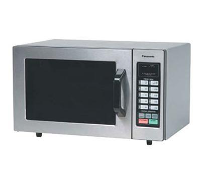
148) Microwave oven
Microwave oven, also called electronic oven, appliance that cooks food by means of high-frequency electromagnetic waves called microwaves. A microwave oven is a relatively small, boxlike oven that raises the temperature of food by subjecting it to a high-frequency electromagnetic field. The microwaves are absorbed by water, fats, sugars, and certain other molecules, whose consequent vibrations produce heat. The heating thus occurs inside the food, without warming the surrounding air; this greatly reduces cooking time, and baking and other cooking tasks that require hours in a conventional oven can be completed in minutes in a microwave oven. Microwave ovens generate radiation at a frequency of about 2,450 megahertz by means of a magnetron, which is a kind of electron tube.
Since the heating occurs by an absorption process, microwave ovens tend to cook certain foods unevenly or at different rates. For example, moist foods cook faster than less moist ones, and moist outer layers tend to absorb most of the radiation before it can reach inner sections, which remain uncooked. Microwave ovens also cannot brown or crisp foods on the outside. Most types of glass, Styrofoam (trademark), polyethylene, paper, and similar materials do not absorb the microwaves and hence do not heat up. Foods cannot be cooked in metal vessels in a microwave oven, however, because the metal blocks out the microwaves. Microwave ovens are subject to safety standards that ensure minimal levels of radiation leakage from them, and no significant health hazards are associated with such leakages.
It appears to me that if one wants to make progress in mathematics, one should study the masters and not the pupils. - Niels Henrik Abel.
Nothing is better than reading and gaining more and more knowledge - Stephen William Hawking.
Offline
#166 2018-07-02 01:20:06
- Jai Ganesh
- Administrator
- Registered: 2005-06-28
- Posts: 53,831
Re: Miscellany
149) Supercomputer
Supercomputer, any of a class of extremely powerful computers. The term is commonly applied to the fastest high-performance systems available at any given time. Such computers have been used primarily for scientific and engineering work requiring exceedingly high-speed computations. Common applications for supercomputers include testing mathematical models for complex physical phenomena or designs, such as climate and weather, evolution of the cosmos, nuclear weapons and reactors, new chemical compounds (especially for pharmaceutical purposes), and cryptology. As the cost of supercomputing declined in the 1990s, more businesses began to use supercomputers for market research and other business-related models.
Distinguishing Features
Supercomputers have certain distinguishing features. Unlike conventional computers, they usually have more than one CPU (central processing unit), which contains circuits for interpreting program instructions and executing arithmetic and logic operations in proper sequence. The use of several CPUs to achieve high computational rates is necessitated by the physical limits of circuit technology. Electronic signals cannot travel faster than the speed of light, which thus constitutes a fundamental speed limit for signal transmission and circuit switching. This limit has almost been reached, owing to miniaturization of circuit components, dramatic reduction in the length of wires connecting circuit boards, and innovation in cooling techniques (e.g., in various supercomputer systems, processor and memory circuits are immersed in a cryogenic fluid to achieve the low temperatures at which they operate fastest). Rapid retrieval of stored data and instructions is required to support the extremely high computational speed of CPUs. Therefore, most supercomputers have a very large storage capacity, as well as a very fast input/output capability.
Still another distinguishing characteristic of supercomputers is their use of vector arithmetic—i.e., they are able to operate on pairs of lists of numbers rather than on mere pairs of numbers. For example, a typical supercomputer can multiply a list of hourly wage rates for a group of factory workers by a list of hours worked by members of that group to produce a list of dollars earned by each worker in roughly the same time that it takes a regular computer to calculate the amount earned by just one worker.
Supercomputers were originally used in applications related to national security, including nuclear weapons design and cryptography. Today they are also routinely employed by the aerospace, petroleum, and automotive industries. In addition, supercomputers have found wide application in areas involving engineering or scientific research, as, for example, in studies of the structure of subatomic particles and of the origin and nature of the universe. Supercomputers have become an indispensable tool in weather forecasting: predictions are now based on numerical models. As the cost of supercomputers declined, their use spread to the world of online gaming. In particular, the 5th through 10th fastest Chinese supercomputers in 2007 were owned by a company with online rights in China to the electronic game World of Warcraft, which sometimes had more than a million people playing together in the same gaming world.
Historical Development
Although early supercomputers were built by various companies, one individual, Seymour Cray, really defined the product almost from the start. Cray joined a computer company called Engineering Research Associates (ERA) in 1951. When ERA was taken over by Remington Rand, Inc. (which later merged with other companies to become Unisys Corporation), Cray left with ERA’s founder, William Norris, to start Control Data Corporation (CDC) in 1957. By that time Remington Rand’s UNIVAC line of computers and IBM had divided up most of the market for business computers, and, rather than challenge their extensive sales and support structures, CDC sought to capture the small but lucrative market for fast scientific computers. The Cray-designed CDC 1604 was one of the first computers to replace vacuum tubes with transistors and was quite popular in scientific laboratories. IBM responded by building its own scientific computer, the IBM 7030—commonly known as Stretch—in 1961. However, IBM, which had been slow to adopt the transistor, found few purchasers for its tube-transistor hybrid, regardless of its speed, and temporarily withdrew from the supercomputer field after a staggering loss, for the time, of $20 million. In 1964 Cray’s CDC 6600 replaced Stretch as the fastest computer on Earth; it could execute three million floating-point operations per second (FLOPS), and the term supercomputer was soon coined to describe it.
Cray left CDC to start Cray Research, Inc., in 1972 and moved on again in 1989 to form Cray Computer Corporation. Each time he moved on, his former company continued producing supercomputers based on his designs.
Cray was deeply involved in every aspect of creating the computers that his companies built. In particular, he was a genius at the dense packaging of the electronic components that make up a computer. By clever design he cut the distances signals had to travel, thereby speeding up the machines. He always strove to create the fastest possible computer for the scientific market, always programmed in the scientific programming language of choice (FORTRAN), and always optimized the machines for demanding scientific applications—e.g., differential equations, matrix manipulations, fluid dynamics, seismic analysis, and linear programming.
Among Cray’s pioneering achievements was the Cray-1, introduced in 1976, which was the first successful implementation of vector processing (meaning, as discussed above, it could operate on pairs of lists of numbers rather than on mere pairs of numbers). Cray was also one of the pioneers of dividing complex computations among multiple processors, a design known as “multiprocessing.” One of the first machines to use multiprocessing was the Cray X-MP, introduced in 1982, which linked two Cray-1 computers in parallel to triple their individual performance. In 1985 the Cray-2, a four-processor computer, became the first machine to exceed one billion FLOPS.
While Cray used expensive state-of-the-art custom processors and liquid immersion cooling systems to achieve his speed records, a revolutionary new approach was about to emerge. W. Daniel Hillis, a graduate student at the Massachusetts Institute of Technology, had a remarkable new idea about how to overcome the bottleneck imposed by having the CPU direct the computations between all the processors. Hillis saw that he could eliminate the bottleneck by eliminating the all-controlling CPU in favour of decentralized, or distributed, controls. In 1983 Hillis cofounded the Thinking Machines Corporation to design, build, and market such multiprocessor computers. In 1985 the first of his Connection Machines, the CM-1 (quickly replaced by its more commercial successor, the CM-2), was introduced. The CM-1 utilized an astonishing 65,536 inexpensive one-bit processors, grouped 16 to a chip (for a total of 4,096 chips), to achieve several billion FLOPS for some calculations—roughly comparable to Cray’s fastest supercomputer.
Hillis had originally been inspired by the way that the brain uses a complex network of simple neurons (a neural network) to achieve high-level computations. In fact, an early goal of these machines involved solving a problem in artificial intelligence, face-pattern recognition. By assigning each pixel of a picture to a separate processor, Hillis spread the computational load, but this introduced the problem of communication between the processors. The network topology that he developed to facilitate processor communication was a 12-dimensional “hypercube”—i.e., each chip was directly linked to 12 other chips. These machines quickly became known as massively parallel computers. Besides opening the way for new multiprocessor architectures, Hillis’s machines showed how common, or commodity, processors could be used to achieve supercomputer results.
Another common artificial intelligence application for multiprocessing was chess. For instance, in 1988 HiTech, built at Carnegie Mellon University, Pittsburgh, Pa., used 64 custom processors (one for each square on the chessboard) to become the first computer to defeat a grandmaster in a match. In February 1996 IBM’s Deep Blue, using 192 custom-enhanced RS/6000 processors, was the first computer to defeat a world champion, Garry Kasparov, in a “slow” game. It was then assigned to predict the weather in Atlanta, Ga., during the 1996 Summer Olympic Games. Its successor (now with 256 custom chess processors) defeated Kasparov in a six-game return match in May 1997.
As always, however, the principal application for supercomputing was military. With the signing of the Comprehensive Test Ban Treaty by the United States in 1996, the need for an alternative certification program for the country’s aging nuclear stockpile led the Department of Energy to fund the Accelerated Strategic Computing Initiative (ASCI). The goal of the project was to achieve by 2004 a computer capable of simulating nuclear tests—a feat requiring a machine capable of executing 100 trillion FLOPS (100 TFLOPS; the fastest extant computer at the time was the Cray T3E, capable of 150 billion FLOPS). ASCI Red, built at Sandia National Laboratories in Albuquerque, N.M., with the Intel Corporation, was the first to achieve 1 TFLOPS. Using 9,072 standard Pentium Pro processors, it reached 1.8 TFLOPS in December 1996 and was fully operational by June 1997.
While the massively multiprocessing approach prevailed in the United States, in Japan the NEC Corporation returned to the older approach of custom designing the computer chip—for its Earth Simulator, which surprised many computer scientists by debuting in first place on the industry’s TOP500 supercomputer speed list in 2002. It did not hold this position for long, however, as in 2004 a prototype of IBM’s Blue Gene/L, with 8,192 processing nodes, reached a speed of about 36 TFLOPS, just exceeding the speed of the Earth Simulator. Following two doublings in the number of its processors, the ASCI Blue Gene/L, installed in 2005 at Sandia National Laboratories in Livermore, Calif., became the first machine to pass the coveted 100 TFLOPS mark, with a speed of about 135 TFLOPS. Other Blue Gene/L machines, with similar architectures, held many of the top spots on successive TOP500 lists. With regular improvements, the ASCI Blue Gene/L reached a speed in excess of 500 TFLOPS in 2007. These IBM supercomputers are also noteworthy for the choice of operating system, Linux, and IBM’s support for the development of open source applications.
The first computer to exceed 1,000 TFLOPS, or 1 petaflop, was built by IBM in 2008. Known as Roadrunner, for New Mexico’s state bird, the machine was first tested at IBM’s facilities in New York, where it achieved the milestone, prior to being disassembled for shipment to the Los Alamos National Laboratory in New Mexico. The test version employed 6,948 dual-core Opteron microchips from Advanced Micro Devices (AMD) and 12,960 of IBM’s Cell Broadband Engines (first developed for use in the Sony Computer Entertainment PlayStation 3 video system). The Cell processor was designed especially for handling the intensive mathematical calculations needed to handle the virtual reality simulation engines in electronic games—a process quite analogous to the calculations needed by scientific researchers running their mathematical models.
Such progress in computing placed researchers on or past the verge of being able, for the first time, to do computer simulations based on first-principle physics—not merely simplified models. This in turn raised prospects for breakthroughs in such areas as meteorology and global climate analysis, pharmaceutical and medical design, new materials, and aerospace engineering. The greatest impediment for realizing the full potential of supercomputers remains the immense effort required to write programs in such a way that different aspects of a problem can be operated on simultaneously by as many different processors as possible. Even managing this in the case of less than a dozen processors, as are commonly used in modern personal computers, has resisted any simple solution, though IBM’s open source initiative, with support from various academic and corporate partners, made progress in the 1990s and 2000s.

It appears to me that if one wants to make progress in mathematics, one should study the masters and not the pupils. - Niels Henrik Abel.
Nothing is better than reading and gaining more and more knowledge - Stephen William Hawking.
Offline
#167 2018-07-03 03:19:27
- Jai Ganesh
- Administrator
- Registered: 2005-06-28
- Posts: 53,831
Re: Miscellany
150) Match
Match, splinter of wood, strip of cardboard, or other suitable flammable material tipped with a substance ignitable by friction.
A match consists of three basic parts: a head, which initiates combustion; a tinder substance to pick up and transmit the flame; and a handle. There are two main types of modern friction matches: (1) strike-anywhere matches and (2) safety matches. The head of the strike-anywhere match contains all the chemicals necessary to obtain ignition from frictional heat, while the safety match has a head that ignites at a much higher temperature and must be struck on a specially prepared surface containing ingredients that pass ignition across to the head. The substance commonly used for obtaining combustion at the temperature of frictional heat is a compound of phosphorus. This substance is found in the head of strike-anywhere matches and in the striking surface of safety matches.
In addition to the phosphoric igniting agent, three other main groups of chemicals are found in the match: (1) oxidizing agents, such as potassium chlorate, which supply oxygen to the igniting agent and the other combustible materials; (2) binders, such as animal glue, starches and gums, and synthetics, which bind the ingredients and are oxidized during combustion; post-combustion binders, such as ground glass, which fuse and hold the ash together, must also be used; and (3) inert materials, such as diatomaceous earth, which provide bulk and regulate the speed of reaction.
Before the invention of matches, it was common to use specially made splinters tipped with some combustible substance, such as sulfur, to transfer a flame from one combustible source to another. An increased interest in chemistry led to experiments to produce fire by direct means on this splinter. Jean Chancel discovered in Paris in 1805 that splints tipped with potassium chlorate, sugar, and gum could be ignited by dipping them into sulfuric acid. Later workers refined this method, which culminated in the “promethean match” patented in 1828 by Samuel Jones of London. This consisted of a glass bead containing acid, the outside of which was coated with igniting composition. When the glass was broken by means of a small pair of pliers, or even with the user’s teeth, the paper in which it was wrapped was set on fire. Other early matches, which could be both inconvenient and unsafe, involved bottles containing phosphorus and other substances. An example was François Derosne’s briquet phosphorique (1816), which used a sulfur-tipped match to scrape inside a tube coated internally with phosphorus.
These first matches were extremely difficult to ignite, and they frequently erupted in a shower of sparks. In addition, the smell was particularly offensive, and the warning printed on Jones’s box (“Persons whose lungs are delicate should by no means use the Lucifers”) seems well founded.
Economic conditions between 1825 and 1835 seem to have favoured the manufacture of matches as an industrial proposition, although the first suppliers fell back on nonphosphoric formulas—i.e., those based mostly on potassium-chlorate mixtures. The first friction matches were invented by John Walker, an English chemist and apothecary, whose ledger of April 7, 1827, records the first sale of such matches. Walker’s “Friction Lights” had tips coated with a potassium chloride–antimony sulfide paste, which ignited when scraped between a fold of sandpaper. He never patented them. Nonphosphoric friction matches were being made by G.-E. Merkel of Paris and J. Siegal of Austria, among others, by 1832, by which time the manufacture of friction matches was well established in Europe.
In 1831 Charles Sauria of France incorporated white, or yellow, phosphorus in his formula, an innovation quickly and widely copied. In 1835 Jànos Irinyi of Hungary replaced potassium chlorate with lead oxide and obtained matches that ignited quietly and smoothly.
The discovery by the Austrian chemist Anton von Schrötter in 1845 of red phosphorus, which is nontoxic and is not subject to spontaneous combustion, led to the safety match, with its separation of the combustion ingredients between the match head and the special striking surface. J.E. Lundström of Sweden patented this method in 1855.
Although safety matches became widely accepted, white phosphorus matches continued to be popular because of their keeping qualities and resistance to climatic conditions. However, at the end of the 19th century serious toxic effects of white phosphorus (“phossy jaw”) were discovered in the factory workers who made such matches. Phosphorus sesquisulfide, much less toxic, was first prepared by the French chemist Georges Lemoine in 1864 but was not used in matches until E.-D. Cahen and H. Sevène of the French government match monopoly filed a patent in 1898; within a few years white phosphorus was outlawed nearly everywhere.
Modern safety matches usually have antimony sulfide, oxidizing agents such as potassium chlorate, and sulfur or charcoal in the heads, and red phosphorus in the striking surface. Nonsafety matches usually have phosphorus sesquisulfide in the heads.
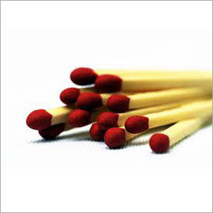
It appears to me that if one wants to make progress in mathematics, one should study the masters and not the pupils. - Niels Henrik Abel.
Nothing is better than reading and gaining more and more knowledge - Stephen William Hawking.
Offline
#168 2018-07-04 21:37:55
- Jai Ganesh
- Administrator
- Registered: 2005-06-28
- Posts: 53,831
Re: Miscellany
151) Electroceramics
Electroceramics, category of advanced ceramic materials that are employed in a wide variety of electric, optical, and magnetic applications. In contrast to traditional ceramic products such as brick and tile, which have been produced in various forms for thousands of years, electroceramics are a relatively recent phenomenon, having been developed largely since World War II. During their brief history, however, they have had a profound impact on the so-called electronics revolution and on the quality of life in developed nations. Electroceramics that have low dielectric constants (i.e., low electric resistivity) are made into substrates for integrated circuits, while electroceramics with high dielectric constants are used in capacitors. Other electroceramic materials exhibit piezoelectricity (the development of strain under an applied field, or vice versa) and are employed in transducers for microphones and other products, while some possess good magnetic properties and are suitable for transformer cores or permanent magnets. Some electroceramics exhibit optical phenomena, such as luminescence (useful in fluorescent lighting) and lasing (exploited in lasers), and still others exhibit changes in optical properties with the application of electric fields and are therefore used extensively as modulators, demodulators, and switches in optical communications.
All the applications listed above require electric insulation, a property that has long been associated with ceramics. On the other hand, many ceramics are suitable for doping by aliovalent materials (that is, materials with other charge states than the ions of the host crystal). Doping can lead to electrically conductive ceramics, which appear in products such as oxygen sensors in automobiles, heating elements in toaster ovens, and transparent oxide films in liquid crystal displays. In addition, ceramics have been developed that are superconducting; that is, they lose all electric resistivity at cryogenic temperatures. Because their critical temperatures (Tc’s; the temperatures at which the transition occurs from resistivity to superconductivity) are much higher than those of conventional metallic superconductors, these ceramic materials are referred to as high-Tc superconductors.
Most electroceramics are truly high-tech materials, insofar as they are made into high value-added items. Starting materials of high purity are employed, often in clean-room processing facilities. Because grain size and grain size distribution can be the deciding factors in the quality of the electroceramic being produced, strict attention is given to the steps of powder processing, consolidation, and firing in order to achieve the desired microstructure. The structure and chemistry of grain boundaries (the areas where two adjacent grains meet) must often be strictly controlled. For example, the segregation of impurities at grain boundaries can have adverse effects on ceramic conductors and superconductors; on the other hand, some ceramic capacitors and varistors depend upon such grain boundary barriers for their operation.
Electroceramic products are described in a number of articles, including electronic substrate and package ceramics, capacitor dielectric and piezoelectric ceramics, magnetic ceramics, optical ceramics, and conductive ceramics.

It appears to me that if one wants to make progress in mathematics, one should study the masters and not the pupils. - Niels Henrik Abel.
Nothing is better than reading and gaining more and more knowledge - Stephen William Hawking.
Offline
#169 2018-07-05 21:15:08
- Jai Ganesh
- Administrator
- Registered: 2005-06-28
- Posts: 53,831
Re: Miscellany
152) Femur
The femur or thigh bone, is the most proximal (closest to the hip joint) bone of the leg in tetrapod vertebrates capable of walking or jumping, such as most land mammals, birds, many reptiles including lizards, and amphibians such as frogs. In vertebrates with four legs such as dogs and horses, the femur is found only in the hindlimbs. The head of the femur articulates with the acetabulum in the pelvic bone forming the hip joint, while the distal part of the femur articulates with the tibia and kneecap forming the knee joint. By most measures the femur is the strongest bone in the body. The femur is also the longest bone in the human body.
Structure
The femur is the only bone in the upper leg. The two femurs converge medially toward the knees, where they articulate with the proximal ends of the tibiae. The angle of convergence of the femora is a major factor in determining the femoral-tibial angle. Human females have wider pelvic bones, causing their femora to converge more than in males. In the condition genu valgum (knock knee) the femurs converge so much that the knees touch one another. The opposite extreme is genu varum (bow-leggedness). In the general population of people without either genu valgum or genu varum, the femoral-tibial angle is about 175 degrees.
The femur is the longest and, by most measures, the strongest bone in the human body. Its length on average is 26.74% of a person's height, a ratio found in both men and women and most ethnic groups with only restricted variation, and is useful in anthropology because it offers a basis for a reasonable estimate of a subject's height from an incomplete skeleton.
The femur is categorised as a long bone and comprises a diaphysis (shaft or body) and two epiphyses (extremities) that articulate with adjacent bones in the hip and knee.
Upper part
The upper or proximal extremity (close to the torso) contains the head, neck, the two trochanters and adjacent structures.
The head of the femur, which articulates with the acetabulum of the pelvic bone, comprises two-thirds of a sphere. It has a small groove, or fovea, connected through the round ligament to the sides of the acetabular notch. The head of the femur is connected to the shaft through the neck or collum. The neck is 4–5 cm. long and the diameter is smallest front to back and compressed at its middle. The collum forms an angle with the shaft in about 130 degrees. This angle is highly variant. In the infant it is about 150 degrees and in old age reduced to 120 degrees on average. An abnormal increase in the angle is known as coxa valga and an abnormal reduction is called coxa vara. Both the head and neck of the femur is vastly embedded in the hip musculature and can not be directly palpated. In skinny people with the thigh laterally rotated, the head of the femur can be felt deep as a resistance profound (deep) for the femoral artery.
The transition area between the head and neck is quite rough due to attachment of muscles and the hip joint capsule. Here the two trochanters, greater and lesser trochanter, are found. The greater trochanter is almost box-shaped and is the most lateral prominent of the femur. The highest point of the greater trochanter is located higher than the collum and reaches the midpoint of the hip joint. The greater trochanter can easily be felt. The trochanteric fossa is a deep depression bounded posteriorly by the intertrochanteric crest on medial surface of the greater trochanter. The lesser trochanter is a cone-shaped extension of the lowest part of the femur neck. The two trochanters are joined by the intertrochanteric crest on the back side and by the intertrochanteric line on the front.
A slight ridge is sometimes seen commencing about the middle of the intertrochanteric crest, and reaching vertically downward for about 5 cm. along the back part of the body: it is called the linea quadrata (or quadrate line).
About the junction of the upper one-third and lower two-thirds on the intertrochanteric crest is the quadrate tubercle located. The size of the tubercle varies and it is not always located on the intertrochanteric crest and that also adjacent areas can be part of the quadrate tubercel, such as the posterior surface of the greater trochanter or the neck of the femur. In a small anatomical study it was shown that the epiphysial line passes directly through the quadrate tubercle.
Body
The body of the femur (or shaft) is long, slender and almost cylindrical in form. It is a little broader above than in the center, broadest and somewhat flattened from before backward below. It is slightly arched, so as to be convex in front, and concave behind, where it is strengthened by a prominent longitudinal ridge, the linea aspera which diverges proximal and distal as the medial and lateral ridge. Proximal the lateral ridge of the linea aspera becomes the gluteal tuberosity while the medial ridge continues as the pectineal line. Besides the linea aspera the shaft has two other bordes; a lateral and medial border. These three bordes separates the shaft into three surfaces: One anterior, one medial and one lateral. Due to the vast musculature of the thigh the shaft can not be palpated.
The third trochanter is a bony projection occasionally present on the proximal femur near the superior border of the gluteal tuberosity. When present, it is oblong, rounded, or conical in shape and sometimes continuous with the gluteal ridge.[6] A structure of minor importance in humans, the incidence of the third trochanter varies from 17–72% between ethnic groups and it is frequently reported as more common in females than in males.
Lower part
The lower extremity of the femur (or distal extremity) is larger than the upper extremity. It is somewhat cuboid in form, but its transverse diameter is greater than its antero-posterior (front to back). It consists of two oblong eminences known as the condyles.
Anteriorly, the condyles are slightly prominent and are separated by a smooth shallow articular depression called the patellar surface. Posteriorly, they project considerably and a deep notch, the Intercondylar fossa of femur, is present between them. The lateral condyle is the more prominent and is the broader both in its antero-posterior and transverse diameters. The medial condyle is the longer and, when the femur is held with its body perpendicular, projects to a lower level. When, however, the femur is in its natural oblique position the lower surfaces of the two condyles lie practically in the same horizontal plane. The condyles are not quite parallel with one another; the long axis of the lateral is almost directly antero-posterior, but that of the medial runs backward and medialward. Their opposed surfaces are small, rough, and concave, and form the walls of the intercondyloid fossa. This fossa is limited above by a ridge, the intercondyloid line, and below by the central part of the posterior margin of the patellar surface. The posterior cruciate ligament of the knee joint is attached to the lower and front part of the medial wall of the fossa and the anterior cruciate ligament to an impression on the upper and back part of its lateral wall.
The articular surface of the lower end of the femur occupies the anterior, inferior, and posterior surfaces of the condyles. Its front part is named the patellar surface and articulates with the patella; it presents a median groove which extends downward to the intercondyloid fossa and two convexities, the lateral of which is broader, more prominent, and extends farther upward than the medial.
Each condyle is surmounted by an elevation, the epicondyle. The medial epicondyle is a large convex eminence to which the tibial collateral ligament of the knee-joint is attached. At its upper part is the adductor tubercle and behind it is a rough impression which gives origin to the medial head of the gastrocnemius. The lateral epicondyle which is smaller and less prominent than the medial, gives attachment to the fibular collateral ligament of the knee-joint.
Development
The femur develops from the limb buds as a result of interactions between the ectoderm and the underlying mesoderm, formation occurs roughly around the fourth week of development.
By the sixth week of development, the first hyaline cartilage model of the femur is formed by chondrocytes. Endochondral ossification begins by the end of the embryonic period and primary ossification centers are present in all long bones of the limbs, including the femur, by the 12th week of development. The hindlimb development lags behind forelimb development by 1–2 days.
Function
As the femur is the only bone in the thigh, it serves as an attachment point for all the muscles that exert their force over the hip and knee joints. Some biarticular muscles – which cross two joints, like the gastrocnemius and plantaris muscles – also originate from the femur. In all, 23 individual muscles either originate from or insert onto the femur.
In cross-section, the thigh is divided up into three separate fascial compartments divided by fascia, each containing muscles. These compartments use the femur as an axis, and are separated by tough connective tissue membranes (or septa). Each of these compartments has its own blood and nerve supply, and contains a different group of muscles. These compartments are named the anterior, medial and posterior fascial compartments.
Clinical significance
Fractures
A femoral fracture that involves the femoral head, femoral neck or the shaft of the femur immediately below the lesser trochanter may be classified as a hip fracture, especially when associated with osteoporosis. Femur fractures can be managed in a pre-hospital setting with the use of a traction splint.
Other animals
In primitive tetrapods, the main points of muscle attachment along the femur are the internal trochanter and third trochanter, and a ridge along the ventral surface of the femoral shaft referred to as the adductor crest. The neck of the femur is generally minimal or absent in the most primitive forms, reflecting a simple attachment to the acetabulum. The greater trochanter was present in the extinct archosaurs, as well as in modern birds and mammals, being associated with the loss of the primitive sprawling gait. The lesser trochanter is a unique development of mammals, which lack both the internal and fourth trochanters. The adductor crest is also often absent in mammals or alternatively reduced to a series of creases along the surface of the bone.
Some species of whales, snakes, and other non-walking vertebrates have vestigial femurs.
One of the earliest known vertebrates to have a femur is the eusthenopteron, a prehistoric lobe-finned fish from the Late Devonian period.
Structures analogous to the third trochanter are present in mammals, including some primates.
Invertebrates
In invertebrate zoology the name femur appears in arthropodology. The usage is not homologous with that of vertebrate anatomy; the term "femur" simply has been adopted by analogy and refers, where applicable, to the most proximal of (usually) the two longest jointed segments of the legs of the arthropoda. The two basal segments preceding the femur are the coxa and trochanter. This convention is not followed in carcinology but it applies in arachnology and entomology. In myriapodology another segment, the prefemur, connects the trochanter and femur.

It appears to me that if one wants to make progress in mathematics, one should study the masters and not the pupils. - Niels Henrik Abel.
Nothing is better than reading and gaining more and more knowledge - Stephen William Hawking.
Offline
#170 2018-07-06 23:58:53
- Jai Ganesh
- Administrator
- Registered: 2005-06-28
- Posts: 53,831
Re: Miscellany
153) Photoelectric Cell
Photoelectric cell or photocell, device whose electrical characteristics (e.g., current, voltage, or resistance) vary when light is incident upon it. The most common type consists of two electrodes separated by a light-sensitive semiconductor material. A battery or other voltage source connected to the electrodes sets up a current even in the absence of light when light strikes the semiconductor section of the photocell, the current in the circuit increases by an amount proportional to the intensity of the light. In the phototube, an older type of photocell, two electrodes are enclosed in a glass tube - an anode and a light-sensitive cathode, i.e., a metal that emits electrons in accordance with the photoelectric effect . Although the phototube itself is now obsolete, the principle survives in the photomultiplier tube, which can be used to detect and amplify faint amounts of light. In this tube, electrons ejected from a photosensitive cathode by light are attracted toward and strike a positive electrode, liberating showers of secondary electrons these are drawn to a more positive electrode, producing yet more secondary electrons - and so on, through several stages, until a large pulse of current is produced. Besides its use in measuring light intensity, a photomultiplier can be built into a television camera tube, making it sensitive enough to pick up the visual image of a star too faint to be seen by the human eye. The photovoltaic type of photoelectric cell, when exposed to light, can generate and support an electric current without being attached to any external voltage source. Such a cell usually consists of a semiconductor with two zones composed of dissimilar materials. When light shines on the semiconductor, a voltage is set up across the junction between the two zones. A phototransistor, which is a type of photovoltaic cell, can generate a small current that acts like the input current in a conventional transistor and controls a larger current in the output circuit. Photovoltaic cells are also used to make solar batteries. Since the current from a photocell can easily be used to operate switches or relays, it is often used in light-actuated counters, automatic door openers, and intrusion alarms. Photocells in such devices are popularly known as electric eyes.
Photoelectric Effect
photoelectric effect, emission of electrons by substances, especially metals, when light falls on their surfaces. The effect was discovered by H. R. Hertz in 1887. The failure of the classical theory of electromagnetic radiation to explain it helped lead to the development of the quantum theory . According to classical theory, when light, thought to be composed of waves, strikes substances, the energy of the liberated electrons ought to be proportional to the intensity of light. Experiments showed that, although the electron current produced depends upon the intensity of the light, the maximum energy of the electrons was not dependent on the intensity. Moreover, classical theory predicted that the photoelectric current should not depend on the frequency of the light and that there should be a time lag between the reception of light on the surface and the emission of the electrons. Neither of these predictions was borne out by experiment. In 1905, Albert Einstein published a theory that successfully explained the photoelectric effect. It was closely related to Planck's theory of blackbody radiation announced in 1900. According to Einstein's theory, the incident light is composed of discrete particles of energy, or quanta, called photons, the energy of each photon being proportional to its frequency according to the equation E = h υ, where E is the energy, υ is the frequency, and h is Planck's constant. Each photoelectron ejected is the result of the absorption of one photon. The maximum kinetic energy, KE, that any photoelectron can possess is given by KE = h υ− W, where W is the work function, i.e., the energy required to free an electron from the material, varying with the particular material. The effect has a number of practical applications, most based on the photoelectric cell .
It appears to me that if one wants to make progress in mathematics, one should study the masters and not the pupils. - Niels Henrik Abel.
Nothing is better than reading and gaining more and more knowledge - Stephen William Hawking.
Offline
#171 2018-07-07 20:55:12
- Jai Ganesh
- Administrator
- Registered: 2005-06-28
- Posts: 53,831
Re: Miscellany
154) Vacuum Cleaner
The humble vacuum cleaner is one of the handiest household cleaning appliances used today. Its simple yet effective design has done away with having to clean dust and other small particles off surfaces by hand, and turned house cleaning into a more efficient and fairly rapid job. Using nothing but suction, the vacuum whisks away dirt and stores it for disposal.
So how do these household heroes work?
Negative pressure
The simplest way to explain how the vacuum cleaner can drag up debris is to think of it like a straw. When you take a sip of drink through a straw, the action of sucking creates a negative air pressure inside the straw: a pressure that is lower than that of the surrounding atmosphere. Just like in space films, where a breach in the spaceship’s hull drags people into space, a vacuum cleaner creates a negative pressure inside, which causes a flow of air into it.
Electric motor
The vacuum cleaner uses an electric motor that spins a fan, sucking in air – and any small particles caught up in it – and pushing it out the other side, into a bag or a canister, to create the negative pressure. You might think then that after a few seconds it would stop working, since you can only force so much air into a confined space. To solve this, the vacuum has an exhaust port that vents the air out the other side, allowing the motor to continue functioning normally.
Filter
The air, however, does not just pass through and get ejected out the other side. It would be very harmful to people using the vacuum. Why? Well, on top of the dirt and grime that a vacuum picks up, it also collects very fine particles that are almost invisible to the eye. If they are inhaled in large enough quantities, they can cause damage to the lungs. Since not all of these particles are trapped by the bag or canister, the vacuum cleaner passes the air through at least one fine filter and often a HEPA (High Efficiency Particulate Arresting) filter to remove almost all of the dust. Only now is the air safe to be breathed again.
Attachments
The power of a vacuum cleaner is determined not just by the power of its motor, but also the size of the intake port, the part that drags up the dirt. The smaller the size of the intake, the more suction power is generated, as squeezing the same amount of air through a narrower passage means that the air must move faster. This is the reason that vacuum cleaner attachments with narrow, small entry ports seem to have a much higher suction than a larger one.
There are many different types of vacuum cleaner, but all of them work on the same principle of creating negative pressure using a fan, trapping the sucked-up dirt, cleaning the exhaust air and then releasing it. The world would be a much dirtier place without them.

It appears to me that if one wants to make progress in mathematics, one should study the masters and not the pupils. - Niels Henrik Abel.
Nothing is better than reading and gaining more and more knowledge - Stephen William Hawking.
Offline
#172 2018-07-09 00:09:32
- Jai Ganesh
- Administrator
- Registered: 2005-06-28
- Posts: 53,831
Re: Miscellany
155) Bleaching Powder
Bleaching powder is chemically, calcium oxychloride (CaOCl2). Bleaching powder is manufactured using Backmann’s plant in which slack lime and Chlorine are made to react to create Bleaching Powder.
Bleaching powder is a yellowish white powder with a strong smell of chlorine. When exposed to air, bleaching powder gives a smell of chlorine. This is because bleaching powder reacts with carbon dioxide from the atmosphere to produce calcium carbonate and chlorine.
How bleaching Powder bleaches?
In the presence of a very small amount of dilute acid, it gives nascent oxygen. Due to the evolution of nascent oxygen, it acts as an oxidising and a bleaching agent.
2CaOCl2 + H2SO4 → CaCl2 + CaSO4 + 2HOCl
2HOCl → 2 HCl + 2 [O]
When it is treated with excess of dilute acids, chlorine is evolved. Chlorine gas produced in this way is known as, “available chlorine” which is responsible for the bleaching action of bleaching power. Available chlorine in bleaching powder is usually 35 – 38% by weight. The strength of bleaching powder is estimated on the basis of available chlorine content.
CaOCl2 + H2SO4→ CaSO4 + H2O + Cl2
CaOCl2 + 2HCl→ CaCl2 + H2O + Cl2
Bleaching powder is used to bleach cotton and linen in textile industry and wood pulp in paper industry. It is also used to bleach washed clothes in laundry. Bleaching powder is also used as a disinfectant and germicide, since it liberates chlorine on exposure to the atmosphere which destroys the germs. It is also used for disinfecting water for the same reason. It is also used as an oxidising agent in many chemical industries.

It appears to me that if one wants to make progress in mathematics, one should study the masters and not the pupils. - Niels Henrik Abel.
Nothing is better than reading and gaining more and more knowledge - Stephen William Hawking.
Offline
#173 2018-07-11 00:06:53
- Jai Ganesh
- Administrator
- Registered: 2005-06-28
- Posts: 53,831
Re: Miscellany
156) Microprocessor
What is a Microprocessor?
A microprocessor is an integrated circuit (IC) which incorporates core functions of a computer’s central processing unit (CPU). It is a programmable multipurpose silicon chip, clock driven, register based, accepts binary data as input and provides output after processing it as per the instructions stored in the memory.
How does a Microprocessor work?
A processor is the brain of a computer which basically consists of Arithmetical and Logical Unit (ALU), Control Unit and Register Array. As the name indicates ALU performs all arithmetic and logical operations on the data received from input devices or memory. Register array consists of a series of registers like accumulator (A), B, C, D etc. which acts as temporary fast access memory locations for processing data. As the name indicates, control unit controls the flow of instructions and data throughout the system.
So basically a microprocessor takes input from input devices, process it as per instructions given in the memory and produces output.
Advantages of a Microprocessor
Low Cost
Microprocessors are available at low cost due to integrated circuit technology. Which will reduce the cost of a computer system.
High Speed
Microprocessor chips can work at very high speed due to the technology involved in it. It is capable of executing millions of instructions per second.
Small Size
Due to very large scale and ultra large scale integration technology, a microprocessor is fabricated in a very less footprint. This will reduce the size of the entire computer system.
Versatile
Microprocessors are very versatile, the same chip can be used for a number of applications by simply changing the program (instructions stored in the memory).
Low Power Consumption
Microprocessors are usually manufactured using metal oxide semiconductor technology, in which MOSFETs (Metal Oxide Semiconductor Field Effect Transistors) are working in saturation and cut off modes. So the power consumption is very low compared to others.
Less Heat Generation
Compared to vacuum tube devices, semiconductor devices won’t emit that much heat.
Reliable
Microprocessors are very reliable, failure rate is very less as semiconductor technology is used.
Portable
Devices or computer system made with microprocessors can be made portable due to the small size and low power consumption.
Common Terms used in a Microprocessor:
Here are some common terms that we will use in microprocessor field.
Bus
A bus is a set of conductors intended to transmit data, address or control information to different elements in a microprocessor. Usually a microprocessor will have 3 types of buses : Data Bus, Control Bus and Address Bus. An 8-bit processor will be using 8-bit wide bus.
Instruction Set
Instruction set is the group of commands that a microprocessor can understand. So instruction set is an interface between hardware and software (program). An instruction commands the processor to switch relevant transistors for doing some processing in data. For eg. ADD A, B; is used to add two numbers stored in the register A and B.
Word Length
Word Length is the number of bits in the internal data bus of a processor or it is the number of bits a processor can process at a time. For eg. An 8-bit processor will have an 8-bit data bus, 8-bit registers and will do 8-bit processing at a time. For doing higher bits (32-bit, 16-bit) operations, it will split that into a series of 8-bit operations.
Cache Memory
Cache memory is a random access memory that is integrated into the processor. So the processor can access data in the cache memory more quickly than from a regular RAM. It is also known as CPU Memory. Cache memory is used to store data or instructions that are frequently referenced by the software or program during the operation. So it will increase the overall speed of the operation.
Clock Speed
Microprocessors uses a clock signal to control the rate at which instructions are executed, synchronize other internal components and to control the data transfer between them. So clock speed refers to the speed at which a microprocessor executes instructions. It is usually measured in Hertz and are expressed in megahertz (MHz), gigahertz (GHz) etc.
Classification of Microprocessors
Based on Word Length
The word length of a processor we can have 8-bit, 16-bit, 32-bit and 64-bit processors.
RISC – Reduced Instruction Set Computer
RISC is a type of microprocessor architecture which uses small, general purpose and highly optimized instruction set rather than more specialized set of instructions found in others. RISC offers high performance over its opposing architecture CISC. In a processor, execution of each instruction require a special circuit to load and process the data. So by reducing instructions, the processor will be using simple circuits and faster in operation.
Simple instruction set
Larger program
Consists of large number of registers
Simple processor circuitry (small number of transistors)
More RAM usage
Fixed length instructions
Simple addressing modes
Usually fixed number of clock cycles for executing one instruction
CISC – Complex Instruction Set Computer
CISC is the opposing microprocessor architecture for RISC. It is made to reduce the number of instructions per program, ignoring the number of cycles per instruction. So complex instructions are directly made into hardware making the processor complex and slower in operation.
This architecture is actually designed to reduce the cost of memory by reducing the program length.
Complex instruction set
Smaller program
Less number of registers
Complex processor circuitry (more number of transistors)
Little RAM usage
Variable length instructions
Variety of addressing modes
Variable number of clock cycles for each instructions
Special Purpose Processors
There are some processors which are designed to handle some specific functions.
DSP – Digital Signal Processors
Coprocessors – processors used along with a main processor (8087 math-coprocessor used with 8086)
Input/Output processors
Transputer – Transistor Computer : Microprocessor with its own local memory.
Examples
Intel 4004 – The First Microprocessor
Intel 8085
Intel 8086
Intel Pentium 4
Intel Core i7
AMD Athlon

It appears to me that if one wants to make progress in mathematics, one should study the masters and not the pupils. - Niels Henrik Abel.
Nothing is better than reading and gaining more and more knowledge - Stephen William Hawking.
Offline
#174 2018-07-13 00:16:59
- Jai Ganesh
- Administrator
- Registered: 2005-06-28
- Posts: 53,831
Re: Miscellany
157) Flight recorder
Flight recorder, by name black box, instrument that records the performance and condition of an aircraft in flight. Governmental regulatory agencies require these devices on commercial aircraft to make possible the analysis of crashes or other unusual occurrences. Flight recorders actually consist of two functional devices, the flight data recorder (FDR) and the voice recorder (CVR), though sometimes these two devices are packaged together in one combined unit. The FDR records many variables, not only basic aircraft conditions such as airspeed, altitude, heading, vertical acceleration, and pitch but hundreds of individual instrument readings and internal environmental conditions. The CVR records verbal communication between crew members within the aircraft’s math as well as voice transmissions by radio. Aircraft sounds audible in the math are also caught on the recorder. Flight recorders are commonly carried in the tail of the aircraft, which is usually the structure that is subject to the least impact in the event of a crash. In spite of the popular name black box, flight recorders are painted a highly visible vermilion colour known as “international orange.”
The voice and instrument data processed by the flight recorder are stored in digital format on solid-state memory boards. Up to 2 hours of sound and 25 hours of flight data are stored, new data continuously replacing the old. The memory boards are housed within a box or cylinder called the crash-survivable memory unit. This is the only truly survivable component of the flight recorder (the other components, such as the data processor, are not necessary for retrieval of data). Consisting of a heavy stainless steel shell wrapped within layers of insulating material and covered by an aluminum housing, a memory unit is expected to survive impacts of 3,400 g (units of gravitational acceleration), flame temperatures as high as 1,100 °C (2,000 °F), and pressures encountered at 6,000 metres (20,000 feet) underwater. In the event of a crash at sea, flight recorders are equipped with a sonar device that is designed to emit an ultrasonic locator signal for at least 30 days.
Flight recorders of varying levels of sophistication have been in existence almost since the beginning of manned flight. The Wright brothers are said to have installed a device on their first flyer of 1903 that logged such parameters as propeller rotation and airspeed, and Charles Lindbergh, in his epoch-making flight across the Atlantic in 1927, employed a barometric device that sensed changes in air pressure (and therefore altitude) and recorded these changes by tracing lines on a rotating spool.
As civil aviation developed in the years before World War II, “crash-survivable” flight recorders came to be seen as a valuable tool in analyzing aviation disasters and contributing to the design of safer aircraft. However, truly serviceable recorders that had any chance of surviving plane crashes were not produced until several years after the war. In the United States, credit for the first survivable FDR is given to James J. Ryan, an engineer employed by General Mills in the early 1950s. Ryan’s VGA Flight Recorder sensed changes in velocity (V), gravitational forces (G), and altitude (A) and inscribed the measurements on a slowly moving strip of aluminum foil. As released in 1953 and sold by General Mills to the Lockheed Aircraft Company, the entire apparatus was enclosed in a yellow-painted spherical shell. Beginning in 1958, larger civilian passenger aircraft in the United States were required to carry survivable FDRs, and numerous other devices were produced employing various recording media, from metal strips to, eventually, magnetic tape.
Parallel developments occurred elsewhere in the world. A series of disastrous crashes of De Havilland Comet jetliners in 1953–54 spurred David Warren, a scientist at Australia’s Aeronautical Research Laboratory (ARL), to design the first combined FDR and CVR. The recording medium for Warren’s ARL Flight Memory Unit was steel wire of the type then being used in magnetic audio recorders. After a demonstration of the device in Britain in 1958, a journalist is said to have given it the sobriquet black box (the common name for all flight recorders to this day), though Warren’s recorder, as produced commercially by S. Davall & Son beginning in 1960, was housed in an egg-shaped casing that was painted red. Other theories of the origin of the term black box have been offered, including the charred appearance of early flight recorders retrieved from a fiery crash.
During the 1960s, crash-protected FDRs and CVRs became mandatory on airliners around the world. Most flight recorders employed magnetic tape, but during the 1990s a great advancement came with the advent of solid-state memory devices. Memory boards are more survivable than recording tape, and the data stored on them can be retrieved quickly by a computer carrying the proper software. A complete picture can be created of conditions on the aircraft during the recorded period, including a computer-animated diagram of the aircraft’s positions and movements. Verbal exchanges and math sounds retrieved from CVR data are transcribed into documents that are made available to investigators along with the actual recordings. The release of these materials to the public is strictly regulated.

It appears to me that if one wants to make progress in mathematics, one should study the masters and not the pupils. - Niels Henrik Abel.
Nothing is better than reading and gaining more and more knowledge - Stephen William Hawking.
Offline
#175 2018-07-15 00:05:31
- Jai Ganesh
- Administrator
- Registered: 2005-06-28
- Posts: 53,831
Re: Miscellany
158) Plimsoll Line
Merchant ships have a marking on their hulls known as the Plimsoll line or the Plimsoll mark, which indicates the limit until which ships can be loaded with enough cargo. Internationally, the Plimsoll line on a ship is officially referred to as the International load line. Every type of ship has a different level of floating and he Plimsoll line on a ship generally varies from one vessel to another.
Technically, no ship is able to absolutely float above, as it travels across the waters. A certain portion of the ship is always immersed in the sea water and the level of submerging is decided by the gross weight of the respective ship. Even the type of water in which the ship is floating influences the application of the load line. Sometimes even the oceanic regions and changing seasons affect the Plimsoll mark, as well. Researchers have found out that the temperature and salinity of the water also plays a key role in deciding the height until which the ship rests in the water.
Why should ships have a Plimsoll line?
The International load line is very essential to ensure safe and smooth sailing of cargo-loaded vessels in the sea. Seafarers should be wary of the fact that the water level should not rise above the line markers due to surcharging of cargo or any technological fault. It might prove to be severely unsafe to the ship as tactless overloading of heavy shipment would sink the ship’s stability. Crossing the assigned limit of the Plimsoll mark or the waterline is considered violation of an international shipping act and can even land the ship’s crew, including the Captain, in deep trouble.
How was the load line used in the past?
Earlier, the line markers used to be marked on the sides of the merchant ships using paint, and the sailors tried to follow the theory that the weight of the cargo should not cause the draught level of the water to rise above the water line. The primary symbol used to indicate the international load line is a circle with horizontally marked line cutting through the center of the respective circle.
How did the International load line become mandatory?
Samuel Plimsoll, a widely known personality and esteemed as the founder of the Plimsoll line, was a famous merchant and also a dedicated shipping reformer. He was an active member for the British Parliament and had influenced the Parliament to formulate The Merchant Shipping Act in the year 1875. He was highly concerned with the safety of the people working in the maritime world. He disliked the organizers of the ships which drowned due to excessive goods that were dumped without any idea about the capacity. He even took the time to conduct some serious research and was grieved to discover the sorry state of affairs. He once found out that nearly a thousand British sailors lose their lives due to the uninformed overloading. Plimsoll was deeply affected by this and he was determined to bring about a change, to protect the sailors. He thus devised the Plimsoll line for types of merchant ships.
According to this reform, all cargo ships should have a load line marked on their hulls, to indicate the limit until which the ships can hold cargo. The line markers points at the maximum depth of safety till which the shipment can be loaded. Thus, Samuel Plimsoll was the pioneer of the concept of the international load line and his contribution holds great significance in the maritime world. The law found great coverage and it was practically applied to the outgoing foreign ships from the ports of Britain, and other countries observing strict nautical standards also started following the international load line rule. The invention of the Plimsoll line proved to be a breakthrough for maintaining safety on board ships, and after it was implemented in Britain, many countries followed the lead, immediately.
In the year of 1930, the International load line was enforced in around 54 countries. In 1968, a new discovery made its rounds in the nautical market. It was an improvisation of the former Plimsoll mark, and involved the application of a smaller load-line for the new bulky ships. The members of the Board of Trade passed an order that the load line was to be painted on all cargo ships. This occurred in the year of 1980.
The contribution of Samuel Plimsoll to the shipping industry is legendary and of great significance. It is due to his sincere efforts that the dangers of ship capsizing were reduced and several lives have been saved at the sea. The Plimsoll line is now deemed mandatory. This symbol is now accepted all over the world and the water line still carries the name of its pioneer, Samuel Plimsoll, as a tribute to the great Member of Parliament.

It appears to me that if one wants to make progress in mathematics, one should study the masters and not the pupils. - Niels Henrik Abel.
Nothing is better than reading and gaining more and more knowledge - Stephen William Hawking.
Offline