Math Is Fun Forum
You are not logged in.
- Topics: Active | Unanswered
#501 2019-09-13 00:24:21
- Jai Ganesh
- Administrator

- Registered: 2005-06-28
- Posts: 53,626
Re: Miscellany
404) Tea
Tea, beverage produced by steeping in freshly boiled water the young leaves and leaf buds of the tea plant, Camellia sinensis. Two principal varieties are used, the small-leaved China plant (C. sinensis sinensis) and the large-leaved Assam plant (C. sinensis assamica). Hybrids of these two varieties are also grown. The leaves may be fermented or left unfermented.
History Of The Tea Trade
According to legend tea has been known in China since about 2700 BCE. For millennia it was a medicinal beverage obtained by boiling fresh leaves in water, but around the 3rd century CE it became a daily drink, and tea cultivation and processing began. The first published account of methods of planting, processing, and drinking came in 350 CE. Around 800 the first seeds were brought to Japan, where cultivation became established by the 13th century. Chinese from Amoy brought tea cultivation to the island of Formosa (Taiwan) in 1810. Tea cultivation in Java began under the Dutch, who brought seeds from Japan in 1826 and seeds, workers, and implements from China in 1833.
In 1824 tea plants were discovered in the hills along the frontier between Burma and the Indian state of Assam. The British introduced tea culture into India in 1836 and into Ceylon (Sri Lanka) in 1867. At first they used seeds from China, but later seeds from the Assam plant were used.
The Dutch East India Company carried the first consignment of China tea to Europe in 1610. In 1669 the English East India Company brought China tea from ports in Java to the London market. Later, teas grown on British estates in India and Ceylon reached Mincing Lane, the centre of the tea trade in London. By the late 19th and early 20th centuries, tea growing had spread to Russian Georgia, Sumatra, and Iran and extended to non-Asian countries such as Natal, Malaŵi, Uganda, Kenya, Congo, Tanzania, and Mozambique in Africa, to Argentina, Brazil, and Peru in South America, and to Queensland in Australia.
Classification Of Teas
Teas are classified according to region of origin, as in China, Ceylon, Japanese, Indonesian, and African tea, or by smaller district, as in Darjeeling, Assam, and Nilgris from India, Uva and Dimbula from Sri Lanka, Keemun from Chi-men in China’s Anhwei Province, and Enshu from Japan.
Teas are also classified by the size of the processed leaf. Traditional operations result in larger leafy grades and smaller broken grades. The leafy grades are flowery pekoe (FP), orange pekoe (OP), pekoe (P), pekoe souchong (PS), and souchong (S). The broken grades are: broken orange pekoe (BOP), broken pekoe (BP), BOP fanning, fannings, and dust. Broken grades usually have substantial contributions from the more tender shoots, while leafy grades come mainly from the tougher and maturer leaves. In modern commercial grading, 95 to 100 percent of production belongs to broken grades, whereas earlier a substantial quantity of leafy grades was produced. This shift has been caused by an increased demand for teas of smaller particle size, which produce a quick, strong brew.
The most important classification is by the manufacturing process, resulting in the three categories of fermented (black), unfermented (green), and semifermented (oolong or pouchong). Green tea is usually produced from the China plant and is grown mostly in Japan, China, and to some extent Malaysia and Indonesia. The infused leaf is green, and the liquor is mild, pale green or lemon-yellow, and slightly bitter. Black tea, by far the most common type produced, is best made from Assam or hybrid plants. The infused leaf is bright red or copper coloured, and the liquor is bright red and slightly astringent but not bitter, bearing the characteristic aroma of tea. Oolong and pouchong teas are produced mostly in southern China and Taiwan from a special variety of the China plant. The liquor is pale or yellow in colour, as in green tea, and has a unique malty, or smoky, flavour.
Processing The Leaf
In tea manufacture, the leaf goes through some or all of the stages of withering, rolling, fermentation, and drying. The process has a twofold purpose: (1) to dry the leaf and (2) to allow the chemical constituents of the leaf to produce the quality peculiar to each type of tea.
The best-known constituent of tea is caffeine, which gives the beverage its stimulating character but contributes only a little to colour, flavour, and aroma. About 4 percent of the solids in fresh leaf is caffeine, and one teacup of the beverage contains 60 to 90 milligrams of caffeine. The most important chemicals in tea are the tannins, or polyphenols, which are colourless, bitter-tasting substances that give the drink its astringency. When acted upon by an enzyme called polyphenol oxidase, polyphenols acquire a reddish colour and form the flavouring compounds of the beverage. Certain volatile oils contribute to the aroma of tea, and also contributing to beverage quality are various sugars and amino acids.
Only black tea goes through all stages of the manufacturing process. Green tea and oolong acquire their qualities through variations in the crucial fermentation stage.
Black tea
Withering
Plucking the leaf initiates the withering stage, in which the leaf becomes flaccid and loses water until, from a fresh moisture content of 70 to 80 percent by weight, it arrives at a withered content of 55 to 70 percent, depending upon the type of processing.
In the traditional process, fresh leaf is spread by hand in thin layers onto trays or sections of coarse fabric called tats. It is then allowed to wither for 18 to 20 hours, depending upon several factors that include the temperature and humidity of the air and the size and moisture content of the leaf. Withering in the open air has been replaced by various mechanized systems. In trough withering, air is forced through a thick layer of leaf on a mesh in a trough. In drum withering, rotating, perforated drums are used instead of troughs, and in tunnel withering, leaf is spread on tats carried by mobile trolleys and is subjected to hot-air blasts in a tunnel. Continuous withering machines move the leaf on conveyor belts and subject it to hot air in an enclosed chamber, discharging withered leaf while fresh leaf is simultaneously loaded.
Mechanized systems greatly reduce withering time, but they can also lower the quality of the final product by reducing the time for chemical withering, during which proteins and carbohydrates break down into simpler amino acids and sugars, and the concentration of caffeine and polyphenols increases.
Rolling
At this stage, the withered leaf is distorted, acquiring the distinctive twist of the finished tea leaf, and leaf cells are burst, resulting in the mixing of enzymes with polyphenols.
The traditional method is to roll bunches of leaves between the hands, or by hand on a table, until the leaf is twisted, evenly coated with juices, and finally broken into pieces. Rolling machines consist of a circular table fitted in the centre with a cone and across the surface with slats called battens. A jacket, or bottomless circular box with a pressure cap, stands atop the table. Table and jacket rotate eccentrically in opposite directions, and the leaf placed in the jacket is twisted and rolled over the cone and battens in a fashion similar to hand rolling. Lumps of rolled leaf are then broken up and sifted. The smaller leaf passing through the sieve—called the fines—is transferred to the fermentation room, and the remaining coarse leaf is rolled again.
In many countries, rolling the leaf has been abandoned in favour of distortion by a variety of machines. In the Legg cutter (actually a tobacco-cutting machine), the leaf is forced through an aperture and cut into strips. The crushing, tearing, and curling (CTC) machine consists of two serrated metal rollers, placed close together and revolving at unequal speeds, which cut, tear, and twist the leaf. The Rotorvane consists of a horizontal barrel with a feed hopper at one end and a perforated plate at the other. Forced through the barrel by a screw-type rotating shaft fitted with vanes at the centre, the leaf is distorted by resistor plates on the inner surface of the barrel and is cut at the end plate. The nontraditional distorting machines can burst leaf cells so thoroughly that in many cases they render the withering stage unnecessary. However, unlike traditional rolling, they do not produce the larger leafy grades of tea.
Fermentation
Fermentation commences when leaf cells are broken during rolling and continues when the rolled leaf is spread on tables or perforated aluminum trays under controlled conditions of temperature, humidity, and aeration. The process actually is not fermentation at all but a series of chemical reactions. The most important is the oxidation by polyphenol oxidase of some polyphenols into compounds that combine with other polyphenols to form orange-red compounds called theaflavins. The theaflavins react with more units to form the thearubigins, which are responsible for the transformation of the leaf to a dark brown or coppery colour. The thearubigins also react with amino acids and sugars to form flavour compounds that may be partly lost if fermentation is prolonged. In general, theaflavin is associated with the brightness and brisk taste of brewed tea, while thearubigin is associated with strength and colour.
In traditional processing, optimum fermentation is reached after two to four hours. This time can be halved in fermenting leaf broken by the Legg cutter, CTC machine, and Rotorvane. In skip fermentation, the leaf is spread in aluminum skips, or boxes, with screened bottoms. Larger boxes are used in trough fermentation, and in continuous fermentation the leaf is spread on trays on a conveyor system. In all of these fermentation systems the leaf is aerated by forced air (oxygen being necessary for the action of the enzymes), and it is brought by automated conveyor to the dryer.
Drying
At this stage, heat inactivates the polyphenol enzymes and dries the leaf to a moisture content of about 3 percent. It also caramelizes sugars, thereby adding flavours to the finished product, and imparts the black colour associated with fermented tea.
Traditionally, fermented leaf was dried on large pans or screens over fire, but since the late 19th century, heated forced air has been used. A mechanized drier consists of a large chamber into the bottom of which hot air is blown as the leaf is fed from the top on a series of descending conveyors. The dried leaf is then cooled quickly to prevent overdrying and loss of quality. Modern innovations on the drier are the hot-feed drier, where hot air is supplied separately to the feeder to arrest fermentation immediately as the leaf is fed, and the fluid-bed drier, where the leaf moves from one end of the chamber to the other over a perforated plate in a liquid fashion.
Green tea
In preparing unfermented tea, the oxidizing enzymes are killed by steamblasting the freshly plucked leaf in perforated drums or by roasting it in hot iron pans prior to rolling. The leaf is then subjected to further heating and rolling until it turns dark green and takes a bluish tint. The leaves are finally dried to a moisture content of 3 to 4 percent and are either crushed into small pieces or ground to a powder.
With the inactivation of polyphenol oxidase, the polyphenols are not oxidized and therefore remain colourless, allowing the processed leaf to remain green. The absence of theaflavins and thearubigins in the finished leaf also gives the beverage a weaker flavour than black tea.
Oolong tea
After a brief withering stage, the leaf is lightly rolled by hand until it becomes red and fragrant. For oolong it is then fermented for about one-half, and for pouchong for one-quarter, of the time allowed for black tea. Fermentation is stopped by heating in iron pans, and the leaf is subjected to more rolling and heating until it is dried.
Packaging
Sorting and grading
The first step in packaging tea is grading it by particle size, shape, and cleanliness. This is carried out on mechanical sieves or sifters fitted with meshes of appropriate size. With small-sized teas in demand, some processed teas are broken or cut again at this stage to get a higher proportion of broken grades. Undesirable particles, such as pieces of tough stalk and fibre, are removed by hand or by mechanical extractor. Winnowing by air removes dust, fibres, and fluff.
Packing
Teas are packed in airtight containers in order to prevent absorption of moisture, which is the principal cause of loss of flavour during storage. Packing chests are usually constructed of plywood, lined with aluminum foil and paper, and sealed with the same material. Also used are corrugated cardboard boxes lined with aluminum foil and paper or paper sacks lined with plastic.
Blended teas are sold to consumers as loose tea, which is packed in corrugated paper cartons lined with aluminum foil, in metal tins, and in fancy packs such as metallized plastic sachets, or they are sold in tea bags made of special porous paper. Tea bags are mainly packed with broken-grade teas.
Instant tea
Instant teas are produced from black tea by extracting the liquor from processed leaves, tea wastes, or undried fermented leaves, concentrating the extract under low pressure, and drying the concentrate to a powder by freeze-drying, spray-drying, or vacuum-drying. Low temperatures are used to minimize loss of flavour and aroma. Instant green teas are produced by similar methods, but hot water is used to extract liquor from powdered leaves. Because all instant teas absorb moisture, they are stored in airtight containers or bottles.
Preparing The Beverage
Blending
Tea sold to the consumer is a blend of as many as 20 to 40 teas of different characteristics, from a variety of estates, and from more than one country. Price is an important factor, with cheap teas (called fillers) used to round off a blend and balance cost. Blends are often designed to be of good average character without outstanding quality, but distinctive blends—for example, with a flavour of seasonal Ceylon tea or the pungency and strength of Assam tea—are also made.
Brewing
A tea infusion is best made by pouring water just brought to the boil over dry tea in a warm teapot and steeping it from three to five minutes. The liquor is separated from the spent leaves and may be flavoured with milk, sugar, or lemon.
Tasting
Professional tasters, sampling tea for the trade, taste but do not consume a light brew in which the liquor is separated from the leaf after five to six minutes. The appearance of both the dry and infused leaf is observed, and the aroma of vapour, colour of liquor, and creaming action (formation of solids when cooled) are assessed. Finally the liquor is taken into the mouth with a sucking noise, swirled around the tongue, brought into contact with the palate, cheek, and gums, and then drawn to the back of the mouth and up to the olfactory nerve in the nose before being expectorated. The liquor is thus felt, tasted, and smelled. Tasters have a large glossary of terms for the evaluation of tea, but the less-demanding consumer drinks it as a thirst quencher and stimulant and for its distinctive sour-harsh taste.

It appears to me that if one wants to make progress in mathematics, one should study the masters and not the pupils. - Niels Henrik Abel.
Nothing is better than reading and gaining more and more knowledge - Stephen William Hawking.
Offline
#502 2019-09-13 15:31:55
- Monox D. I-Fly
- Member

- From: Indonesia
- Registered: 2015-12-02
- Posts: 2,000
Re: Miscellany
The most important chemicals in tea are the tannins, or polyphenols, which are colourless, bitter-tasting substances that give the drink its astringency.
I heard that tannin is good for combating snake venom...
Actually I never watch Star Wars and not interested in it anyway, but I choose a Yoda card as my avatar in honor of our great friend bobbym who has passed away.
May his adventurous soul rest in peace at heaven.
Offline
#503 2019-09-14 00:01:13
- Jai Ganesh
- Administrator
- Registered: 2005-06-28
- Posts: 53,626
Re: Miscellany
ganesh wrote:The most important chemicals in tea are the tannins, or polyphenols, which are colourless, bitter-tasting substances that give the drink its astringency.
I heard that tannin is good for combating snake venom...
Is it so? I don't know.
It appears to me that if one wants to make progress in mathematics, one should study the masters and not the pupils. - Niels Henrik Abel.
Nothing is better than reading and gaining more and more knowledge - Stephen William Hawking.
Offline
#504 2019-09-15 00:20:07
- Jai Ganesh
- Administrator
- Registered: 2005-06-28
- Posts: 53,626
Re: Miscellany
405) Camera
Camera, in photography, device for recording an image of an object on a light-sensitive surface; it is essentially a light-tight box with an aperture to admit light focused onto a sensitized film or plate.
Though there are many types of cameras, all include five indispensable components: (1) the camera box, which holds and protects the sensitive film from all light except that entering through the lens; (2) film, on which the image is recorded, a light-sensitive strip usually wound on a spool, either manually or automatically, as successive pictures are taken; (3) the light control, consisting of an aperture or diaphragm and a shutter, both often adjustable; (4) the lens, which focuses the light rays from the subject onto the film, creating the image, and which is usually adjustable by moving forward or back, changing the focus; and (5) the viewing system, which may be separate from the lens system (usually above it) or may operate through it by means of a mirror.
The earliest camera was the camera obscura, which was adapted to making a permanent image by Joseph Nicéphore Niepce and Louis-Jacques-Mandé Daguerre of France in the 1820s and 1830s. Many improvements followed in the 19th century, notably flexible film, developed and printed outside the camera. In the 20th century a variety of cameras was developed for many different purposes, including aerial photography, document copying, and scientific research.
Camera, lightproof box or container, usually fitted with a lens, which gathers incoming light and concentrates it so that it can be directed toward the film (in an optical camera) or the imaging device (in a digital camera) contained within. Today there are many different types of camera in use, all of them more or less sophisticated versions of the camera obscura, which dates back to antiquity. Nearly all of them are made up of the same basic parts: a body (the lightproof box), a lens and a shutter to control the amount of light reaching the light-sensitive surface, a viewfinder to frame the scene, and a focusing mechanism.
Still Cameras
Focusing and Composing the Scene
Except for pinhole cameras, which focus the image on the film through a tiny hole, all other cameras use a lens for focusing. The focal length of a lens, i.e., the distance between the rear of the lens (when focused on infinity) and the film (or imaging device), determines the angle of view and the size of objects as they appear on the imaging surface. The image is focused on that surface by adjusting the distance between the lens and the surface. In most 35-mm cameras (among the most widely used of modern optical cameras) and digital cameras this is done by rotating the lens, thus moving it closer to or farther from the film or imaging device. With twin-lens reflex and larger view cameras, the whole lens and the panel to which it is attached are moved toward or away from the film.
To view the subject for composing (and, usually, to help bring it into focus) nearly every camera has some kind of viewfinder. One of the simplest types, employed in most view cameras, is a screen that is placed on the back of the camera and replaced by the film in making the exposure. This time-consuming procedure is avoided in the modern 35-mm single-lens (and other) reflex cameras by placing the screen in a special housing on top of the camera. Inside the camera, in front of the film plane, there is a movable mirror that bounces the image from the lens to the screen for viewing and focusing, and then flips out of the way when the shutter is tripped, so that the image hits the film instead of the mirror. The mirror returns automatically to place after the exposure has been made. In rangefinder cameras the subject is generally viewed by means of two separate windows, one of which views the scene directly and the other of which contains an adjustable optical mirror device. When this device is adjusted by rotating the lens, the image entering through the lens can be brought into register, at the eyepiece, with the image from the direct view, thereby focusing the subject on the film. Digital cameras have an optical viewfinder, a liquid crystal display (LCD) screen, or both. Optical viewfinders are common in point-and-shoot cameras. An LCD screen allows the user see the photograph's content before the picture is taken and after, allowing the deletion of unwanted pictures.
Controlling the Light Entering the Camera
The speed of a lens is indicated by reference to its maximum opening, or aperture, through which light enters the camera. This aperture, or f-stop, is controlled by an iris diaphragm (a series of overlapping metal blades that form a circle with a hole in the center whose diameter can be increased or decreased as desired) inside the lens. The higher the f-stop number, the smaller the aperture, and vice versa.
A shutter controls the time during which light is permitted to enter the camera. There are two basic types of shutter, leaf-type and focal-plane. The leaf-type shutter employs a ring of overlapping metal blades similar to those of the iris diaphragm, which may be closed or opened to the desired degree. It is normally located between the lens elements but occasionally is placed behind or in front of the lens. The focal-plane shutter is located just in front of the film plane and has one or two cloth or metal curtains that travel vertically or horizontally across the film frame. By adjusting the shutter speed in conjunction with the width of aperture, the proper amount of light (determined by using a light meter and influenced by the relative sensitivity of the film being used) for a good exposure can be obtained.
Features of Modern Cameras
Most of today's 35-mm cameras, both rangefinder and reflex models, incorporate a rapid film-transport mechanism, lens interchangeability (whereby lenses of many focal lengths, such as wide-angle and telephoto, may be used with the same camera body), and a built-in light meter. Many also have an automatic exposure device whereby either the shutter speed or the aperture is regulated automatically (by means of a very sophisticated solid-state electronics system) to produce the "correct" exposure. Accessories include filters, which correct for deficiencies in film sensitivity; flash bulbs and flash mechanisms for supplying light; and monopods and tripods, for steady support.
Simple box cameras, including cameras of the Eastman Kodak Instamatic type, are fixed-focus cameras with limited or no control over exposure. Twin-lens reflex cameras use one lens solely for viewing, while the other focuses the image on the film. Also very popular are compact 35-mm rangefinder cameras; 126 cartridge cameras; and the subminiature cameras, including the 110 "pocket" variation of the Instamatic type and the Minox, which uses 9.5-mm film. Other categories in use include roll- and sheet-film single-lens reflex (SLR) cameras that use 120 and larger size films; self-processing Polaroid cameras; press cameras and view cameras that use 21/4 × 31/4 in., 4 × 5 in., 5 × 7 in., 8 × 10 in., and 11 × 14 in. film sizes; stereo cameras, the double slides from which require a special viewer; and various special types such as the super wide-angle and the panoramic cameras. (The numbers 110, 120, and 126 are film-size designations from the manufacturer and do not refer to actual measurements.) Digital cameras are essentially no different in operation but capture the image electronically rather than via a photographic emulsion.
The smaller, pocket-sized, automatic cameras of the Advanced Photo System (APS), introduced in 1996, are unique in that they are part of an integrated system. Using magnetic strips on the film to communicate with the photofinishing equipment, the camera can communicate shutter speed, aperture setting, and lighting conditions for each frame to the computerized photofinishing equipment, which can then compensate to avoid over- or underexposed photographic prints. Basic features of the APS cameras are drop-in loading, three print formats (classic, or 4 by 6 in.; hi vision, or 4 by 7 in.; and panoramic, or 4 by 11.5 in.) at the flick of a switch, and auto-focus, auto-exposure, "point-and-shoot" operation.
Digital cameras have several unique features. Resolution is made up of building blocks called pixels, one million of which are called a megapixel. Digital cameras have resolutions ranging from less than one megapixel to greater than seven megapixels. With more megapixels, more picture detail is captured, resulting in sharper, larger prints. Focus is a function of "zoom." Most digital cameras have an optical zoom, a digital zoom, or both. An optical zoom lens actually moves outward toward the subject to take sharp close-up photographs; this is the same kind of zoom lens found in traditional cameras. Digital zoom is a function of software inside the camera that crops the edges from a photograph and electronically enlarges the center portion of the image to fill the frame, resulting in a photograph with less detail. Some models also have a macro lens for close-ups of small, nearby objects. Storage of digital photographs may be in the camera's internal memory or in removable magnetic cards, sticks, or disks. These images can be transferred to a computer for viewing and editing or may be viewed on the camera's liquid crystal display. Digital cameras typically also have the ability to record video, but have less storage capacity and fewer video features than camcorders.
The marriage of microelectronics and digital technology led to the development of the camera phone, a cellular telephone that also has picture- (and video-) taking capability; smartphones, which integrate a range of applications into a cellphone, also typically include a camera. Some such phones can immediately send the picture to another camera phone or computer via the Internet or through the telephone network, offering the opportunity to take and share pictures in real time. Unlike the traditional camera, and to some extent the equivalent digital camera, which are used primarily for scheduled events or special occasions, the camera phone is available for impromptu or unanticipated photographic opportunities.
Motion Picture Cameras
The motion picture camera comes in a variety of sizes, from 8 mm to 35 mm and 75 mm. Motion picture film comes in spools or cartridges. The spool type, employed mostly in 16- and 35-mm camera systems, must be threaded through the camera and attached to the take-up spool by hand, whereas a film cartridge—available for the super-8-mm systems—avoids this procedure. In all modern movie cameras the film is driven by a tiny electric motor that is powered by batteries.
Motion picture cameras all operate on the same basic principles. Exposures are usually made at a rate of 18 or 24 frames per second (fps), which means that as the film goes through the camera it stops for a very brief moment to expose each frame. This is accomplished in nearly all movie cameras by a device called a rotary shutter—basically a half-circle of metal that spins, alternately opening and closing an aperture, behind which is located the film. To make the film travel along its path and hold still for the exposure of each frame, a device called a claw is required. This is another small piece of metal that alternately pops into the sprocket holes or perforations in the film, pulls the film down, retracts to release the film while the frame is being exposed, and finally returns to the top of the channel in which it moves to grasp the next frame. The movement of the shutter and claw are synchronized, so that the shutter is closed while the claw is pulling the frame downward and open for the instant that the frame is motionless in its own channel or gate.
Lenses for movie cameras also come in "normal," wide-angle, and long focal lengths. Some older cameras had a turret on which were mounted all three lens types. The desired lens could be fixed into position by simply rotating the turret. Many super-8 cameras come with a single zoom lens, incorporating a number of focal lengths that are controlled by moving a certain group of lens elements toward or away from the film. Most of these cameras have an automatic exposure device that regulates the f-stop according to the reading made by a built-in electric eye. Movie camera lenses are focused in the same way as are still camera lenses. For viewing purposes, a super-8 uses a beam splitter—a partially silvered reflector that diverts a small percentage of the light to a ground-glass viewfinder while allowing most of the light to reach the film. Other cameras have a mirror-shutter system that transmits all the light, at intervals, alternately to film and viewfinder. Many of the super-8 cameras also contain some kind of rangefinder, built into the focusing screen, for precise focusing.
Development of the Camera
The original concept of the camera dates from Grecian times, when Aristotle referred to the principle of the camera obscura [Lat.,=dark chamber] which was literally a dark box—sometimes large enough for the viewer to stand inside—with a small hole, or aperture, in one side. (A lens was not employed for focusing until the Middle Ages.) An inverted image of a scene was formed on an interior screen; it could then be traced by an artist. The first diagram of a camera obscura appeared in a manuscript by Leonardo da Vinci in 1519, but he did not claim its invention.
The recording of a negative image on a light-sensitive material was first achieved by the Frenchman Joseph Nicéphore Niepce in 1826; he coated a piece of paper with asphalt and exposed it inside the camera obscura for eight hours. Although various kinds of devices for making pictures in rapid succession had been employed as early as the 1860s, the first practical motion picture camera—made feasible by the invention of the first flexible (paper base) films—was built in 1887 by E. J. Marey, a Frenchman. Two years later Thomas Edison invented the first commercially successful camera. However, cinematography was not accessible to amateurs until 1923, when Eastman Kodak produced the first 16-mm reversal safety film, and Bell & Howell introduced cameras and projectors with which to use it. Systems using 8-mm film were introduced in 1923; super-8, with its smaller sprocket holes and larger frame size, appeared in 1965. A prototype of the the digital camera was developed in 1975 by Eastman Kodak, but digital cameras were not commercialized until the 1990s. Since then they have gradually superseded many film-based cameras, both for consumers and professionals, leading many manufacturers to eliminate or reduce the number of the film cameras they produce.

It appears to me that if one wants to make progress in mathematics, one should study the masters and not the pupils. - Niels Henrik Abel.
Nothing is better than reading and gaining more and more knowledge - Stephen William Hawking.
Offline
#505 2019-09-17 00:06:18
- Jai Ganesh
- Administrator
- Registered: 2005-06-28
- Posts: 53,626
Re: Miscellany
406) Button Cell
A watch battery or button cell is a small single cell battery shaped as a squat cylinder typically 5 to 25 mm (0.197 to 0.984 in) in diameter and 1 to 6 mm (0.039 to 0.236 in) high — resembling a button. A metal can forms the bottom body and positive terminal of the cell. An insulated top cap is the negative terminal.
Button cells are used to power small portable electronics devices such as wrist watches, pocket calculators, artificial cardiac pacemakers, implantable cardiac defibrillators, automobile keyless entry transmitters, and hearing aids. Wider variants are usually called coin cells. Devices using button cells are usually designed around a cell giving a long service life, typically well over a year in continuous use in a wristwatch. Most button cells have low self-discharge and hold their charge for a long time if not used. Relatively high-power devices such as hearing aids may use a zinc–air battery which have much higher capacity for a given size, but dry out after a few weeks even if not used.
Button cells are single cells, usually disposable primary cells. Common anode materials are zinc or lithium. Common cathode materials are manganese dioxide, silver oxide, carbon monofluoride, cupric oxide or oxygen from the air. Mercuric oxide button cells were formerly common, but are no longer available due to the toxicity and environmental effects of mercury.
Cells of different chemical composition made in the same size are mechanically interchangeable. However, the composition can affect service life and voltage stability. Using the wrong cell may lead to short life or improper operation (for example, light metering on a camera requires a stable voltage, and silver cells are usually specified). Sometimes different cells of the same type and size and specified capacity in milliampere-hour (mAh) are optimised for different loads by using different electrolytes, so that one may have longer service life than the other if supplying a relatively high current.
Button cells are very dangerous for small children. Button cells that are swallowed can cause severe internal burns and significant injury or death.
Properties of cell chemistries
Alkaline batteries are made in the same button sizes as the other types, but typically provide less capacity and less stable voltage than more costly silver oxide or lithium cells. They are often sold as watch batteries, and bought by people who do not know the difference.
Silver cells may have very stable output voltage until it suddenly drops very rapidly at end of life. This varies for individual types; one manufacturer (Energizer) offers three silver oxide cells of the same size, 357-303, 357-303H and EPX76, with capacities ranging from 150 to 200 mAh, voltage characteristics ranging from gradually reducing to fairly constant, and some stated to be for continuous low drain with high pulse on demand, others for photo use.
Mercury batteries also supply a stable voltage, but are now banned in many countries due to their toxicity and environmental impact.
Zinc-air batteries use air as the depolarizer and have much higher capacity than other types, as they take that air from the atmosphere. Cells have an air-tight seal which must be removed before use; cells will then dry out in a few weeks, regardless of use.
For comparison, the properties of some cells from one manufacturer of different types with diameter 11.6 mm and height 5.4 mm are listed:
• Silver: capacity 200 mAh to an end-point of 0.9 V, internal resistance 5–15 ohms, weight 2.3 g
• Alkaline (manganese dioxide): 150 mAh (0.9), 3–9 ohms, 2.4 g
• Mercury: 200 mAh, 2.6 g
• Zinc-air: 620 mAh, 1.9 g
Examining datasheets for a manufacturer's range may show a high-capacity alkaline cell with a capacity as high as one of the lower-capacity silver types; or a particular silver cell with twice the capacity of some particular alkaline cell. If the powered equipment requires a relatively high voltage (e.g., 1.3 V) to operate correctly, a silver cell with a flat discharge characteristic will give much longer service than an alkaline cell—even if it has the same specified capacity in mAh to an end-point of 0.9 V. If some device seems to "eat up" batteries after the original supplied by the manufacturer is replaced, it may be useful to check the device's requirements and the replacement battery's characteristics. For digital calipers, in particular, some are specified to require at least 1.25 V to operate, others 1.38 V.
While alkaline, silver oxide, and mercury batteries of the same size may be mechanically interchangeable in any given device, use of a cell of the right voltage but unsuitable characteristics can lead to short battery life or failure to operate equipment. Common lithium batteries, with a terminal voltage around 3 volts, are not made in sizes interchangeable with 1.5 volt cells. Use of a battery of significantly higher voltage than equipment is designed for can cause permanent damage.
Type designation
International standard IEC 60086-3 defines an alphanumeric coding system for "Watch batteries". Manufacturers often have their own naming system; for example, the cell called LR1154 by the IEC standard is named AG13, LR44, 357, A76, and other names by different manufacturers. The IEC standard and some others encode the case size so that the numeric part of the code is uniquely determined by the case size; other codes do not encode size directly.
Electrochemical system
For types with stable voltage falling precipitously at end-of-life (cliff-top voltage-versus-time graph), the end-voltage is the value at the "cliff-edge", after which the voltage drops extremely rapidly. For types which lose voltage gradually (slope graph, no cliff-edge) the end-point is the voltage beyond which further discharge will cause damage to either the battery or the device it is powering, typically 1.0 or 0.9 V.
Common names are conventional rather than uniquely descriptive; for example, a silver (oxide) cell has an alkaline electrolyte.
L, S, and C type cells are today the most commonly used types in quartz watches, calculators, small PDA devices, computer clocks, and blinky lights. Miniature zinc-air batteries – P type – are used in hearing aids and medical instruments. In the IEC system, larger cells may have no prefix for the chemical system, indicating they are zinc-carbon batteries; such types are not available in button cell format.
The second letter, R, indicates a round (cylindrical) form.
The standard only describes primary batteries. Rechargeable types made in the same case size will carry a different prefix not given in the IEC standard, for example some ML and LiR button cells use rechargeable lithium technology.
Package size
Package size of button batteries using standard names is indicated by a 2-digit code representing a standard case size, or a 3- or 4-digit code representing the cell diameter and height. The first one or two digits encode the outer diameter of the battery in whole millimeters, rounded down; exact diameters are specified by the standard, and there is no ambiguity; e.g., any cell with an initial 9 is 9.5 mm in diameter, no other value between 9.0 and 9.9 is used. The last two digits are the overall height in tenths of a millimeter.
Examples:
• CR2032: lithium, 20 mm diameter, 3.2 mm height
• CR2025: lithium, 20 mm diameter, 2.5 mm height
• SR516: silver, 5.8 mm diameter, 1.6 mm height
• LR1154/SR1154: alkaline/silver, 11.6 mm diameter, 5.4 mm height. The two-digit codes LR44/SR44 are often used for this size
Some coin cells, particularly lithium, are made with solder tabs for permanent installation, such as to power memory for configuration information of a device. The complete nomenclature will have prefixes and suffixes to indicate special terminal arrangements. For example, there is a plug-in and a solder-in CR2032, a plug-in and three solder-in BR2330s in addition to CR2330s, and many rechargeables in 2032, 2330, and other sizes.
Letter suffix
After the package code, the following additional letters may optionally appear in the type designation to indicate the electrolyte used:
• P: potassium hydroxide electrolyte
• S: sodium hydroxide electrolyte
• No letter: organic electrolyte
• W: the battery complies with all the requirements of the international IEC 60086-3 standard for watch batteries.
Other package markings
Apart from the type code described in the preceding section, watch batteries should also be marked with
• the name or trademark of the manufacturer or supplier;
• the polarity (+);
• the date of manufacturing.
Date codes
Often a 2-letter code (sometimes on the side of the battery) where the first letter identifies the manufacturer and the second is the year of manufacture. For example:
• YN – the letter N is the 14th letter in the alphabet – indicates the cell was manufactured in 2014.
There is no universal standard.
The manufacturing date can be abbreviated to the last digit of the year, followed by a digit or letter indicating the month, where O, Y, and Z are used for October, November and December, respectively (e.g., 01 = January 1990 or January 2000, 9Y = November 1999 or November 2009).
Common manufacturer code
A code used by some manufacturers is AG (alkaline) or SG (silver) followed by a number, where 1 equates to standard 621, 2 to 726, 3 to 736, 4 to 626, 5 to 754, 6 to 920 or 921, 7 to 926 or 927, 8 to 1120 or 1121, 9 to 936, 10 to 1130 or 1131, 11 to 721, 12 to 1142, and 13 to 1154. To those familiar with the chemical symbol for silver, Ag, this may suggest incorrectly that AG cells are silver.
Common applications
• Timekeeping
o Electric wristwatches, both digital and analogue
o Backup power for personal computer real time clocks
• Backup power for SRAM
o Backup power for personal computer BIOS configuration data
o Various video game cartridges or memory cards where battery-powered RAM is used to store data
o PCMCIA static RAM memory cards
• Lighting
o Laser pointers
o Small LED flashlights
o Solar/electric candles
o LED Bicycle head or tail lighting
o Red dot sights and electronic spotting scopes
• Pocket computers
o Calculators
o Small PDA devices
o Cyclocomputers
• Hearing aids
• Some remote controls, especially for keyless entry
• Various electronic toys (like Tamagotchi, Pokémon Pikachu or a Pokéwalker and other various digital pet devices)
• Battery-operated children's books
• Glucometers
• Security tokens
• Heart rate monitors
• Manual cameras with light meters
• LED throwies
• Digital thermometers
• Digital altimeter
• Electronic tuner for musical instruments
Rechargeable variants
In addition to disposable (single use) button cells, rechargeable batteries in many of the same sizes are available, with lower capacity than disposable cells. Disposable and rechargeable batteries are manufactured to fit into a holder or with solder tags for permanent connection. In equipment with a battery holder, disposable or rechargeable batteries may be used, if the voltage is compatible.
A typical use for a small rechargeable battery (in coin or other format) is to back up the settings of equipment which is normally permanently mains-powered, in the case of power failure. For example, many central heating controllers store operation times and similar information in volatile memory, lost in the case of power failure. It is usual for such systems to include a backup battery, either a disposable in a holder (current drain is extremely low and life is long) or a soldered-in rechargeable.
Rechargeable NiCd button cells were often components of the backup battery of older computers; non-rechargeable lithium button cells with a lifetime of several years are used in later equipment.
Chargeable batteries typically have the same dimension-based numeric code with different letters; thus CR2032 is a disposable battery while ML2032, VL2032 and LIR2032 are rechargeables that fit in the same holder if not fitted with solder tags. It is mechanically possible, though hazardous, to fit a disposable battery in a holder intended for a rechargeable; holders are fitted in parts of equipment only accessible by service personnel in such cases.
Health issues
In large metropolitan regions small children are directly impacted by the improper disposal of button cell type batteries, with Auckland in NZ getting about 20 cases per year requiring hospitalization.
Small children are likely to swallow button cells, which are somewhat visually similar to sweets, often causing fatalities. In Greater Manchester, England, with a population of 2,700,000, has had two children between 12 months and six years old that have died and five suffered life-changing injuries in the 18 months leading up to October 2014. In the United States, on average over 3,000 pediatric button batteries ingestions are reported each year with a trend toward major and fatal outcomes increasing. Coin cells of diameter 20 mm or greater cause the most serious injuries, even if dead or not crushed.
Mercury or cadmium
Some button cells contain mercury or cadmium, which are toxic. In early 2013 the European Parliament Environment Committee voted for a ban on the export and import of a range of mercury-containing products such as button cells and other batteries to be imposed from 2020.
Lithium
Lithium cells, if ingested, are highly dangerous. In the pediatric population, of particular concern is the potential for one of these batteries to get stuck in the oesophagus. Such impactions can rapidly devolve and cause severe tissue injury in as little as 2 hours. The damage is caused, not by the contents of the battery, but by the electric current that is created when the anode (negative) face of the battery comes in contact with the electrolyte-rich esophageal tissue. The surrounding water undergoes a hydrolysis reaction that produces a sodium hydroxide (caustic soda) build up near the battery's anode face. This results in the liquefactive necrosis of the tissue, a process whereby the tissue effectively is melted away by the alkaline solution. Severe complications can occur, such as erosion into nearby structures like the trachea or major blood vessels, the latter of which can cause fatal bleeds. While the only cure for an esophageal impaction is endoscopic removal, a recent study out of Children's Hospital of Philadelphia by Rachel R. Anfang and colleagues found that early and frequent ingestion of honey or sucralfate suspension prior to removal can reduce the injury severity to a significant degree. As a result of these findings, US-based National Capital Poison Center (Poison Control) updated its triage and treatment guideline for button battery ingestions to include the administration of honey and/or sucralfate as soon as possible after a known or suspected ingestion. Prevention efforts in the US by the National Button Battery Task force in cooperation with industry leaders have led to changes in packaging and battery compartment design in electronic devices to reduce a child's access to these batteries. However, there still is a lack of awareness across the general population and medical community to its dangers. Central Manchester University Hospital Trust warns that "a lot of doctors are unaware that this can cause harm".

It appears to me that if one wants to make progress in mathematics, one should study the masters and not the pupils. - Niels Henrik Abel.
Nothing is better than reading and gaining more and more knowledge - Stephen William Hawking.
Offline
#506 2019-09-19 00:10:56
- Jai Ganesh
- Administrator
- Registered: 2005-06-28
- Posts: 53,626
Re: Miscellany
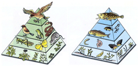
407) Food Chain
A food chain is a linear network of links in a food web starting from producer organisms (such as grass or trees which use radiation from the Sun to make their food) and ending at apex predator species (like grizzly bears or killer whales), detritivores (like earthworms or woodlice), or decomposer species (such as fungi or bacteria). A food chain also shows how the organisms are related with each other by the food they eat. Each level of a food chain represents a different trophic level. A food chain differs from a food web, because the complex network of different animals' feeding relations are aggregated and the chain only follows a direct, linear pathway of one animal at a time. Natural interconnections between food chains make it a food web. A common metric used to the quantify food web trophic structure is food chain length. In its simplest form, the length of a chain is the number of links between a trophic consumer and the base of the web and the mean chain length of an entire web is the arithmetic average of the lengths of all chains in a food web.
Many food webs have a keystone species (Such as Sharks) . A keystone species is a species that has a large impact on the surrounding environment and can directly affect the food chain. If this keystone species dies off it can set the entire food chain off balance. Keystone species keep herbivores from depleting all of the foliage in their environment and preventing a mass extinction.
Food chains were first introduced by the Arab scientist and philosopher Al-Jahiz in the 10th century and later popularized in a book published in 1927 by Charles Elton, which also introduced the food web concept.
Food chain length
The food chain's length is a continuous variable that provides a measure of the passage of energy and an index of ecological structure that increases in value counting progressively through the linkages in a linear fashion from the lowest to the highest trophic (feeding) levels.
Food chains are often used in ecological modeling (such as a three species food chain). They are simplified abstractions of real food webs, but complex in their dynamics and mathematical implications.
Ecologists have formulated and tested hypotheses regarding the nature of ecological patterns associated with food chain length, such as increasing length increasing with ecosystem size, reduction of energy at each successive level, or the proposition that long food chain lengths are unstable. Food chain studies have an important role in ecotoxicology studies tracing the pathways and biomagnification of environmental contaminants.
Producers, such as plants, are organisms that utilize solar or chemical energy to synthesize starch. All food chains must start with a producer. In the deep sea, food chains centered on hydrothermal vents and cold seeps exist in the absence of sunlight. Chemosynthetic bacteria and archaea use hydrogen sulfide and methane from hydrothermal vents and cold seeps as an energy source (just as plants use sunlight) to produce carbohydrates; they form the base of the food chain. Consumers are organisms that eat other organisms. All organisms in a food chain, except the first organism, are consumers.
In a food chain, there is also reliable energy transfer through each stage. However, all the energy at one stage of the chain is not absorbed by the organism at the next stage. The amount of energy from one stage to another decreases.
It appears to me that if one wants to make progress in mathematics, one should study the masters and not the pupils. - Niels Henrik Abel.
Nothing is better than reading and gaining more and more knowledge - Stephen William Hawking.
Offline
#507 2019-09-21 00:12:17
- Jai Ganesh
- Administrator
- Registered: 2005-06-28
- Posts: 53,626
Re: Miscellany
408) Lighthouse
Lighthouse, structure, usually with a tower, built onshore or on the seabed to serve as an aid to maritime coastal navigation, warning mariners of hazards, establishing their position, and guiding them to their destinations. From the sea a lighthouse may be identified by the distinctive shape or colour of its structure, by the colour or flash pattern of its light, or by the coded pattern of its radio signal. The development of electronic navigation systems has had a great effect on the role of lighthouses. Powerful lights are becoming superfluous, especially for landfall, but there has been a significant increase in minor lights and lighted buoys, which are still necessary to guide the navigator through busy and often tortuous coastal waters and harbour approaches. Among mariners there is still a natural preference for the reassurance of visual navigation, and lighted marks also have the advantages of simplicity, reliability, and low cost. In addition, they can be used by vessels with no special equipment on board, providing the ultimate backup against the failure of more sophisticated systems.
History Of Lighthouses
Lighthouses of antiquity
The forerunners of lighthouses proper were beacon fires kindled on hilltops, the earliest references to which are contained in the Iliad and the Odyssey (c. 8th century BCE). The first authenticated lighthouse was the renowned Pharos of Alexandria, which stood some 350 feet (about 110 metres) high. The Romans erected many lighthouse towers in the course of expanding their empire, and by 400 CE there were some 30 in service from the Black Sea to the Atlantic. These included a famous lighthouse at Ostia, the port of Rome, completed in 50 CE, and lighthouses at Boulogne, France, and Dover, England. A fragment of the original Roman lighthouse at Dover still survives.
The Phoenicians, trading from the Mediterranean to Great Britain, marked their route with lighthouses. These early lighthouses had wood fires or torches burning in the open, sometimes protected by a roof. After the 1st century CE, candles or oil lamps were used in lanterns with panes of glass or horn.
Medieval lighthouses
The decline of commerce in the Dark Ages halted lighthouse construction until the revival of trade in Europe about 1100 CE. The lead in establishing new lighthouses was taken by Italy and France. By 1500, references to lighthouses became a regular feature of books of travel and charts. By 1600, at least 30 major beacons existed.
These early lights were similar to those of antiquity, burning mainly wood, coal, or torches in the open, although oil lamps and candles were also used. A famous lighthouse of this period was the Lanterna of Genoa in Italy, probably established about 1139. It was rebuilt completely in 1544 as the impressive tower that remains a conspicuousseamark today. The keeper of the light in 1449 was Antonio Columbo, uncle of the Columbus who crossed the Atlantic. Another early lighthouse was built at Meloria, Italy, in 1157, which was replaced in 1304 by a lighthouse on an isolated rock at Livorno. In France the Roman tower at Boulogne was repaired by the emperor Charlemagne in 800. It lasted until 1644, when it collapsed owing to undermining of the cliff. The most famous French lighthouse of this period was one on the small island of Cordouan in the estuary of the Gironde River near Bordeaux. The original was built by Edward the Black Prince in the 14th century. In 1584 Louis de Foix, an engineer and architect, undertook the construction of a new light, which was one of the most ambitious and magnificent achievements of its day. It was 135 feet in diameter at the base and 100 feet high, with an elaborate interior of vaulted rooms, richly decorated throughout with a profusion of gilt, carved statuary, and arched doorways. It took 27 years to build, owing to subsidence of the apparently substantial island. By the time the tower was completed in 1611, the island was completely submerged at high water. Cordouan thus became the first lighthouse to be built in the open sea, the true forerunner of such rock structures as the Eddystone Lighthouse.
The influence of the Hanseatic League helped increase the number of lighthouses along the Scandinavian and German coasts. At least 15 lights were established by 1600, making it one of the best-lighted areas of that time.
During this period, lights exhibited from chapels and churches on the coast frequently substituted for lighthouses proper, particularly in Great Britain.
The beginning of the modern era
The development of modern lighthouses can be said to have started about 1700, when improvements in structures and lighting equipment began to appear more rapidly. In particular, that century saw the first construction of towers fully exposed to the open sea. The first of these was Henry Winstanley’s 120-foot-high wooden tower on the notorious Eddystone Rocks off Plymouth, England. Although anchored by 12 iron stanchions laboriously grouted into exceptionally hard red rock, it lasted only from 1699 to 1703, when it was swept away without a trace in a storm of exceptional severity; its designer and builder, in the lighthouse at the time, perished with it. It was followed in 1708 by a second wooden tower, constructed by John Rudyerd, which was destroyed by fire in 1755. Rudyerd’s lighthouse was followed by John Smeaton’s famous masonry tower in 1759. Smeaton, a professional engineer, embodied an important new principle in its construction whereby masonry blocks were dovetailed together in an interlocking pattern. Despite the dovetailing feature, the tower largely relied on its own weight for stability—a principle that required it to be larger at the base and tapered toward the top. Instead of a straight conical taper, though, Smeaton gave the structure a curved profile. Not only was the curve visually attractive, but it also served to dissipate some of the energy of wave impact by directing the waves to sweep up the walls.
Owing to the undermining of the foundation rock, Smeaton’s tower had to be replaced in 1882 by the present lighthouse, constructed on an adjacent part of the rocks by Sir James N. Douglass, engineer-in-chief of Trinity House. In order to reduce the tendency of waves to break over the lantern during severe storms (a problem often encountered with Smeaton’s tower), Douglass had the new tower built on a massive cylindrical base that absorbed some of the energy of incoming seas. The upper portion of Smeaton’s lighthouse was dismantled and rebuilt on Plymouth Hoe, where it still stands as a monument; the lower portion or “stump” can still be seen on the Eddystone Rocks.
Following the Eddystone, masonry towers were erected in similar open-sea sites, which include the Smalls, off the Welsh coast; Bell Rockin Scotland; South Rock in Ireland; and Minots Ledge off Boston, Massachusetts, U.S. The first lighthouse of the North American continent, built in 1716, was on the island of Little Brewster, also off Boston. By 1820 there were an estimated 250 major lighthouses in the world.
Modern Lighthouses
Construction
While masonry and brick continue to be employed in lighthouse construction, concrete and steel are the most widely used materials. Structurally well suited and reasonably cheap, concrete especially lends itself to aesthetically pleasing designs for shore-based lighthouses.
Modern construction methods have considerably facilitated the building of lighthouses in the open sea. On soft ground, the submerged caisson method is used, a system applied first in 1885 to the building of the Roter Sand Lighthouse in the estuary of the Weser River in Germany and then to the Fourteen Foot Bank light in the Delaware Bay, U.S. With this method, a steel caisson or open-ended cylinder, perhaps 40 feet in diameter, is positioned on the seabed. By excavation of sand, it is sunk into the seabed to a depth of possibly 50 feet. At the same time, extra sections are added to the top as necessary so that it remains above high water level. The caisson is finally pumped dry and filled with concrete to form a solid base on which the lighthouse proper is built.
Where the seabed is suitable, it is possible to build a “float out” lighthouse, consisting of a cylindrical tower on a large concrete base that can be 50 feet in diameter. The tower is constructed in a shore berth, towed out to position, and then sunk to the seabed, where the base is finally filled with sand. Weighing 5,000 tons (4.5 million kilograms) or more, these towers rely on their weight for stability and require a leveled, prepared seabed. For greater stability during towing, the cylindrical tower itself often consists of two or more telescopic sections, raised to full height by hydraulic jacks after being founded on the seabed. This design was pioneered largely in Sweden.
Another design, which is more independent of seabed conditions, is the conventional steel-piled structure used for offshore gas and oil rigs. Piles may be driven as deep as 150 feet into the seabed, depending on the underlying strata. The United States has built about 15 light towers of this type, one prominent example being Ambrose Light off New York.
Helicopters are widely employed in the servicing and maintenance of offshore towers, so that modern designs normally include a helipad. In fact, older cylindrical masonry structures of the previous era—including the Eddystone tower—have had helipads fitted above their lanterns.
Illuminants
Wood fires were not discontinued until 1800, though after about 1550 coal, a more compact and longer-burning fuel, was increasingly favoured, particularly in northwestern Europe. A lighthouse in those days could consume 300 tons or more of coal a year. In full blaze, the coal fire was far superior to other forms of lighting, preferred by mariners to oil or candles. The disadvantage of both coal fires and early oil lamps and candles was the prodigious amount of smoke produced, which resulted in rapid blackening of the lantern panes, obscuring the light.
Oil lamps
In 1782 a Swiss scientist, Aimé Argand, invented an oil lamp whose steady smokeless flame revolutionized lighthouse illumination. The basis of his invention was a circular wick with a glass chimney that ensured an adequate current of air up the centre and the outside of the wick for even and proper combustion of the oil. Eventually, Argand burners with as many as 10 concentric wicks were designed. These lamps originally burned fish oil, later vegetable oil, and by 1860 mineral oil. The Argand burner became the principal lighthouse illuminant for more than 100 years.
In 1901 the Briton Arthur Kitson invented the vaporized oil burner, which was subsequently improved by David Hood of Trinity House and others. This burner utilized kerosene vaporized under pressure, mixed with air, and burned to heat an incandescent mantle. The effect of the vaporized oil burner was to increase by six times the power of former oil wick lights. (The principle is still widely used for such utensils as camp stoves and pressure lamps.)
Gas lamps
Early proposals to use coal gas at lighthouses did not meet with great success. A gasification plant at the site was usually impracticable, and most of the lights were too remote for a piped supply. However, acetylene gas, generated in situ from calcium carbide and water, came into use around the turn of the 20th century, and its use increased following the introduction of the dissolved acetylene process, which by dissolving the acetylene in acetone made it safe to compress for storage.
Acetylene gas as a lighthouse illuminant had a profound influence on the advancement of lighthouse technology, mainly through the work of Gustaf Dalén of Sweden, who pioneered its application between 1900 and 1910. Burned either as an open flame or mixed with air in an incandescent mantle, acetylene produced a light equal to that of oil. Its great advantage was that it could be readily controlled; thus, for the first time automatic unattended lights were possible. Dalén devised many ingenious mechanisms and burners, operating from the pressure of the gas itself, to exploit the use of acetylene. Most of the equipment he designed is still in general use today. One device is an automatic mantle exchanger that brings a fresh mantle into use when the previous one burns out. Another, economizing on gas, was the “sun valve,” an automatic day-night switch capable of extinguishing the light during the day. The switch utilized the difference in heat-absorbing properties between a dull black surface and a highly polished one, producing a differential expansion arranged by suitable mechanical linkage to control the main gas valve.
The acetylene system facilitated the establishment of many automatic unattended lighthouses in remote and inaccessible locations, normally requiring only an annual visit to replenish the storage cylinders and overhaul the mechanism. Liquefied petroleum gas, such as propane, has also found use as an illuminant, although both oil and gas lamps have largely been superseded by electricity.
Electric lamps
Electric illumination in the form of carbon arc lamps was first employed at lighthouses at an early date, even while oil lamps were still in vogue. The first of these was at South Foreland, England, in 1858, followed by a number of others. The majority of these, however, were eventually converted to oil, since the early arc lamps were difficult to control and costly to operate. In 1913 the Helgoland Lighthouse in the North Sea off Germany was equipped with arc lamps and searchlight mirrors to give a light of 38 million candlepower, the most powerful lighthouse in the world at that time.
The electric-filament lamp, which came into general use in the 1920s, is now the standard illuminant. Power output ranges from about 1,500 watts for the largest structures down to about 5 watts for buoys and minor beacons. Most lamps are of the tungsten-halogen type for better efficiency and longer life. As new types of electric lamps become available—for example, compact source discharge tube lamps—they are adopted for lighthouse use wherever suitable.
Optical equipment
Paraboloidal mirrors
With the advent of the Argand burner, a reliable and steady illuminant, it became possible to develop effective optical apparatuses for increasing the intensity of the light. In the first equipment of this type, known as the catoptric system, paraboloidal reflectors concentrated the light into a beam. In 1777 William Hutchinson of Liverpool, England, produced the first practical mirrors for lighthouses, consisting of a large number of small facets of silvered glass set in a plaster cast molded to a paraboloid form. More generally, shaped metal reflectors were used, silvered or highly polished. These were prone, however, to rapid deterioration from heat and corrosion; the glass facet reflector, although not as efficient, lasted longer. The best metallic reflectors available in 1820 were constructed of heavily silvered copper in the proportion of 6 ounces of silver to 16 ounces of copper (compared with the 0.5 ounce of silver to 16 ounces of copper commonly used for plated tableware of the period). With such heavy plating, cleaning cloths were kept for subsequent recovery of the silver. These mirrors could increase the intensity of an Argand burner, nominally about five candlepower, almost 400 times.
Although the mirror could effectively concentrate the light into an intense beam, it was necessary to rotate it to make it visible from any direction. This produced the now familiar revolving lighthouse beam, with the light appearing as a series of flashes. Mariners were not favourably disposed to these early flashing lights, contending that a fixed steady light was essential for a satisfactory bearing. However, the greatly increased intensity and the advantage of using a pattern of flashes to identify the light gradually overcame their objections. The first revolving-beam lighthouse was at Carlsten, near Marstrand, Sweden, in 1781.
Rectangular and drum lenses
In 1821 Augustin Fresnel of France produced the first apparatus using the refracting properties of glass, now known as the dioptric system, or Fresnel lens. On a lens panel he surrounded a central bull’s-eye lens with a series of concentric glass prismatic rings. The panel collected light emitted by the lamp over a wide horizontal angle and also the light that would otherwise escape to the sky or to the sea, concentrating it into a narrow, horizontal pencil beam. With a number of lens panels rotating around the lamp, he was then able in 1824 to produce several revolving beams from a single light source, an improvement over the mirror that produces only a single beam. To collect more of the light wasted vertically, he added triangular prism sections above and below the main lens, which both refracted and reflected the light. By doing this he considerably steepened the angle of incidence at which rays shining up and down could be collected and made to emerge horizontally. Thus emerged the full Fresnel catadioptric system, the basis of all lighthouse lens systems today. To meet the requirement for a fixed all-around light, in 1836 English glassmaker William Cookson modified Fresnel’s principle by producing a cylindrical drum lens, which concentrated the light into an all-around fan beam. Although not as efficient as the rectangular panel, it provided a steady, all-around light. Small drum lenses, robust and compact, are widely used today for buoy and beacon work, eliminating the complication of a rotating mechanism; instead of revolving, their lights are flashed on and off by an electronic code unit.
Prior to Fresnel’s invention the best mirror systems could produce a light of about 20,000 candlepower with an Argand burner. The Fresnel lens system increased this to 80,000 candlepower, roughly equivalent to a modern automobile headlamp; with the pressure oil burner, intensities of up to 1,000,000 candlepower could be achieved. For a light of this order, the burner mantle would measure 4 inches (100 millimetres) in diameter. The rotating lens system would have four large Fresnel glass lens panels, 12 feet high, mounted about four feet from the burner on a revolving lens carriage. The lens carriage would probably weigh five tons, about half of it being the weight of the glass alone. The rotating turntable would float in a circular cast-iron trough containing mercury. With this virtually frictionless support bearing, the entire assembly could be smoothly rotated by weight-driven clockwork. If the illuminant was acetylene gas, the lens rotation could be driven by gas pressure.
Installations of this type are still in common use, although many have been converted to electric lamps with electric-motor drives. Modern lens equipment of the same type is much smaller, perhaps 30 inches (75 centimetres) high, mounted on ball bearings and driven by an electric motor. With a 250-watt lamp, illumination of several hundred thousand candlepower can be readily obtained. Lens panels can be molded in transparent plastic, which is lighter and cheaper. Drum lenses are also molded in plastic. In addition, with modern techniques, high-quality mirrors can be produced easily and cheaply.
Intensity, visibility, and character of lights
Geographic range and luminous range
The luminous intensity of a light, or its candlepower, is expressed in international units called candelas. Intensities of lighthouse beams can vary from thousands to millions of candelas. The range at which a light can be seen depends upon atmospheric conditions and elevation. Since the geographic horizon is limited by the curvature of the Earth, it can be readily calculated for any elevation by standard geometric methods. In lighthouse work the observer is always assumed to be at a height of 15 feet, although on large ships he may be 40 feet above the sea. Assuming a light at a height of 100 feet, the range to an observer at 15 feet above the horizon will be about 16 nautical miles. This is known as the geographic range of the light. (One nautical mile, the distance on the Earth’s surface traversed by one minute of arc longitude or latitude, is equivalent to 1.15 statute miles or 1.85 kilometres.)
The luminous range of a light is the limiting range at which the light is visible under prevailing atmospheric conditions and disregarding limitations caused by its height and the Earth’s curvature. A very powerful light, low in position, can thus have a clear-weather luminous range greater than that when first seen by the mariner on the horizon. Powerful lights can usually be seen over the horizon because the light is scattered upward by particles of water vapour in the atmosphere; this phenomenon is known as the loom of the light.
Atmospheric conditions have a marked effect on the luminous range of lights. They are defined in terms of a transmission factor, which is expressed as a percentage up to a maximum of 100 percent (representing a perfectly clear atmosphere, never attained in practice). Clear weather in the British Isles corresponds to about 80 percent transmission, but in tropical regions it can rise to 90 percent, increasing the luminous range of a 10,000-candela light from 18 to 28 nautical miles. Conversely, in mist or haze at about 60 percent transmission, a light of 1,000,000 candelas would be necessary to maintain a luminous range of 18 nautical miles. In dense fog, with visibility down to 100 yards or metres, a light of 10,000,000,000 candelas could scarcely be seen at half a nautical mile. Because average clear-weather conditions vary considerably from one region of the world to another, luminous ranges of all lighthouses by international agreement are quoted in an arbitrary standard clear-weather condition corresponding to a daytime meteorological visibility of 10 nautical miles, or 74 percent transmission. This is known as the nominal range of a light. Mariners use conversion tables to determine the actual luminous range in the prevailing visibility.
Because lights of very great intensity yield diminishing returns in operational effectiveness, most very high-powered lights have been abandoned. A maximum of 100,000 candelas, with a clear-weather range of 20 nautical miles, is generally considered adequate. Nevertheless, there are still some very high-powered lights, which for special reasons may have to be visible at a distance in daylight.
Identification
Most lighthouses rhythmically flash or eclipse their lights to provide an identification signal. The particular pattern of flashes or eclipses is known as the character of the light, and the interval at which it repeats itself is called the period. The number of different characters that can be used is restricted by international agreement through the International Association of Lighthouse Authorities in Paris, to which the majority of maritime nations belong. The regulations are too lengthy to quote in full, but essentially a lighthouse may display a single flash, regularly repeated at perhaps 5-, 10-, or 15-second intervals. This is known as a flashing light. Alternatively, it may exhibit groups of two, three, or four flashes, with a short eclipse between individual flashes and a long eclipse of several seconds between successive groups. The whole pattern is repeated at regular intervals of 10 or 20 seconds. These are known as group-flashing lights. In another category, “occulting” lights are normally on and momentarily extinguished, with short eclipses interrupting longer periods of light. Analogous to the flashing mode are occulting and group-occulting characters. A special class of light is the isophase, which alternates eclipses and flashes of exactly equal duration.
Steadily burning lights are called fixed lights. For giving mariners accurate directional information in ports, harbours, and estuarial approaches, fixed directional lights display sharply defined red and green sectors. Another sensitive and very accurate method of giving directional instruction is by range lights, which are two fixed lights of different elevation located about half a nautical mile apart. The navigator steers the vessel to keep the two lights aligned one above the other. Laser lights are also employed in this role.
Another use for fixed lights is the control of shipping at harbourentrances. A traffic signal consists of a vertical column of high-powered red, green, and yellow projector lights that are visible in daylight.
The daymark requirement of a lighthouse is also important; lighthouse structures are painted to stand out against the prevailing background. Shore lighthouses are usually painted white for this purpose, but in the open sea or against a light background conspicuous bands of contrasting colours, usually red or black, are utilized.
Sound signals
The limitations of purely visual navigation very early led to the idea of supplementary audible warning in lighthouses. The first sound signals were explosive. At first cannon were used, and later explosive charges were attached to retractable booms above the lantern and detonated electrically. Sometimes the charges contained magnesium in order to provide an accompanying bright flare. Such signals could be heard up to four nautical miles away. Bells also were used, the striker being actuated by weight-driven clockwork or by a piston driven by compressed gas (usually carbon dioxide). Some bells were very large, weighing up to one ton.
Compressed air
About the beginning of the 20th century, compressed air fog signals, which sounded a series of blasts, were developed. The most widely used were the siren and the diaphone. The siren consisted of a slotted rotor revolving inside a slotted stator that was located at the throat of a horn. The diaphone worked on the same principle but used a slotted piston reciprocating in a cylinder with matching ports. The largest diaphones could be heard under good conditions up to eight nautical miles away. Operating pressures were at 2 to 3 bars (200 to 300 kilopascals), and a large diaphone could consume more than 50 cubic feet (approximately 1.5 cubic metres) of air per second. This required a large and powerful compressing plant, 50 horsepower or more, with associated air-storage tanks.
A later compressed-air signal was the tyfon. Employing a metal diaphragm vibrated by differential air pressure, it was more compact and efficient than its predecessors.
Electricity
Modern fog signals are almost invariably electric. Like the tyfon, they employ a metal diaphragm, but in the electric signal they vibrate between the poles of an electromagnet that is energized by alternating current from an electronic power unit. Powers range from 25 watts to 4 kilowatts, with ranges from half a nautical mile to five nautical miles. Note frequencies lie between 300 and 750 hertz. Emitters can be stacked vertically, half a wavelength apart, in order to enhance the sound horizontally and reduce wasteful vertical dispersion.
Effective range
Propagation of sound in the open air is extremely haphazard, owing to the vagaries of atmospheric conditions. Wind direction, humidity, and turbulence all have an effect. Vertical wind and temperature gradients can bend the sound up or down; in the latter case it can be reflected off the sea, resulting in shadow zones of silence. The range of audibility of a sound signal is therefore extremely unpredictable. Also, it is difficult to determine with any precision the direction of a signal, especially from the bridge of a ship in fog.
Radio aids
Sophisticated and complex radio navigation systems such as Decca and Loran, and satellite-based global positioning systems such as Navstar, are not properly within the field of lighthouses. Radio and radar beacons, on the other hand, provide the equivalent of a visual seamark that is unaffected by visibility conditions.
Radio beacons
Radio beacons, which first appeared in the 1920s, transmit in the frequency band of 285–315 kilohertz. In a characteristic signal lasting one minute, the station identification, in Morse code, is transmitted two or three times, followed by a period of continuous transmission during which a bearing can be taken by a ship’s direction-finding receiver. Bearing accuracy averages better than 3°. The frequency of transmission varies in different parts of the world. In the busy waters of Europe, radio beacons transmit continuously on a number of different channels within the allotted frequency band.
Since the development of satellite-based positioning systems in the 1970s and ’80s, the early importance of radio beacons as an aid for marine navigators has diminished considerably—although they have acquired a second important role in broadcasting corrections for improving the accuracy of the satellite systems. The principal users of radio beacons are now small-craft operators, particularly recreational sailors.
Radar responders
Radar-responder beacons are employed in other fields, such as aviation; in marine navigation they are called racons. A racon transmits only in response to an interrogation signal from a ship’s radar, at the time when the latter’s rotating scanner bears on it. During this brief period, the racon receives some 10 radar pulses, in reaction to which it transmits back a coded reply pulse that is received and displayed on the ship’s radar screen. Racons operate on both marine radar bands of 9,300–9,500 megahertz and 2,900–3,100 megahertz. A racon can greatly increase the strength of the echo from a poor radar target, such as a small buoy; it is also helpful in ranging on and identifying positions on inconspicuous and featureless coastlines and in identifying offshore oil and gas rigs.
The first racons came into use in 1966, and there are now many hundreds in service. Early racons, employing vacuum-tube technology, were large and required several hundred watts of power. Modern racons, using solid-state electronics, are compact and light, typically 16 by 24 inches in area and 20 to 35 pounds (10 to 15 kilograms) in weight. They draw an average of one watt in power from low-voltage batteries.
Passive radar echo enhancers are also used on poor targets, such as buoys. They are made up of flat metal sheets joined into polyhedral shapes whose geometry is such as to reflect as much of the radar pulse as possible. A typical array, some 28 by 24 inches overall, can have an echoing area equivalent to that of a flat sheet with an area of some 1,600 square feet (150 square metres).
Automation
The acetylene-gas illumination system, being fully automatic and reliable, enabled automatic lights to be operated early on. Its main use today is in buoys, which inherently have to operate unattended. Automation on a large scale, bringing considerable savings in operating costs, came after the advent of electrical equipment and technology and the demise of compressed-air fog signals. Unattended lights are now designed to be automatic and self-sustaining, with backup plant brought on-line automatically upon failure of any component of the system. The status of the station is monitored from a remote control centre via landline, radio, or satellite link. Power is provided from public electricity supplies (where practicable), with backup provided by diesel generators or storage batteries. Where solar power with storage batteries is used, the batteries must have sufficient capacity to operate the light during the hours of darkness. In tropical and subtropical regions, day and night are of approximately equal duration throughout the year, but in temperate and polar regions the days become longer and the nights shorter during the summer, and vice versa in winter. In these areas, solar power has to operate on an annual “balance sheet” basis, with excess charge being generated and stored in large batteries during the summer so that a reserve can be drawn upon in winter. Canada and Norway successfully operate solar-powered lights of this type in their Arctic regions.
Floating lights
Floating lights (i.e., lightships and buoys) have an important function in coastal waters, guiding both passing ships and those making for or leaving harbour. They have the great advantage of mobility and can readily be redeployed to meet changed conditions. For example, submerged hazards such as sandbanks can move over the years under the influence of the sea, and, for vessels of very deep draft, safe channels must be correctly marked around these hazards at all times.
Lightships
Lightships originated in the early 17th century, arising from the need to establish seamarks in positions where lighthouses were at that time impracticable. The first lightship, established in 1732 at Nore Sand in the Thames estuary, was rapidly followed by others. These early vessels were small converted merchant or fishing vessels showing lanterns suspended from crossarms at the masthead. Not until 1820 were vessels built specifically as lightships.
Modern lightships are in most cases an alternative to costly seabed structures. Used to mark the more important hazards and key positions in traffic patterns, they are capable of providing a range of powerful aids. Power is provided by diesel generators. Lightships vary in size but can be up to 150 feet in length, 25 feet in beam, and 500 tons in displacement. They are not normally self-propelled, most often being towed into position and moored by a single chain and anchor. They need to be withdrawn for overhaul every two or three years.
Lightships are costly items to operate and to maintain and are therefore prime candidates for automation. All lightships are now unattended, and the power of their lights and fog signals has been downgraded to a more appropriate level—e.g., 10,000 candelas for the lights, giving a luminous range of approximately 15 nautical miles, and sound signals with a range of two nautical miles. New lightships are of similar construction to the older type but are smaller—60 feet or less in length. The smallest sizes, 30 feet or less, are intended for sheltered waters and are often known as light floats.
Buoys
Buoys are used to mark safe channels, important reference points, approaches to harbours, isolated dangers and wrecks, and areas of special significance. They also mark traffic lanes in narrow and congested waters where traffic routing is in force (i.e., where ships are being routed into designated lanes with entry and exit points).
Structure and operation
Usually constructed of quarter-inch steel plate, buoys vary in diameter from three to six feet and can weigh as much as eight tons. They are moored to a two- or three-ton concrete or cast-iron sinker by a single length of chain, which is normally about three times as long as the depth of water. Size and type depend on the application. Buoys in deep water need to be large in order to provide buoyancy sufficient to support the extra weight of chain. Stability is provided by a circular “skirt keel,” with possibly a ballast weight. The light is mounted on a superstructure some 10 feet above the waterline. For more powerful lights on the open sea or deep water, the light may be 15 or 20 feet above the waterline in order to increase the range. Known as “high focal plane” buoys, for stability they require a cylindrical tail tube extending downward some 10 feet from the bottom of the hull.
Buoys are also manufactured from fibreglass-reinforced plastic. They have the advantage of light weight, hence lighter moorings (often of synthetic cable), ease of handling, and resistance to corrosion. Fibreglass buoys are generally confined to sheltered waters.
In addition to the light, a buoy may be fitted with a racon, radar reflector, and low-power fog signal. In earlier times acetylene gas was the only practicable illuminant, which restricted the power of the light. Modern electric buoy lights range in power from a few hundred candelas up to the region of 1,000 candelas, giving ranges of eight nautical miles or so. The lighting equipment consists of a drum lens, usually made of plastic and between 4 and 12 inches in diameter, along with a low-voltage lamp of 5 to 60 watts. Power can be provided by expendable primary batteries, which need to be replaced every year or two. In order to increase the service interval and also to accommodate more powerful lights, rechargeable batteries with onboard generators are used. Some tail-tube buoys, which tend to oscillate vertically with the motion of the sea, generate power from the oscillating water column in the tube. The water column produces an oscillating air column, which in turn drives a small air-turbine generator. However, the vast majority of buoys are solar-powered, and buoys constitute the major part of solar-powered lights.
Buoyage systems
A buoy’s colour and profile and the colour and flash pattern of its light convey information to navigators. The beginnings of a unified system of buoy marking emerged in 1889, but it was not until 1936 that a worldwide unified system was agreed upon at the League of Nations in Geneva. World War II began before the agreement could be fully ratified, and in the aftermath of the war little progress was made. At one time there were nine different systems in use. By 1973, however, a number of spectacular marine accidents urged the international community into action, and by 1980 a new unified system had been agreed upon by 50 maritime countries.
Maintained by the International Association of Lighthouse Authorities, the Maritime Buoyage System applies two nearly identical standards to two regions. Region A comprises Europe, Australia, New Zealand, Africa, the Persian Gulf, and most Asian states. Region B includes the Americas, Japan, Korea, and the Philippines. In both regions, the buoyage systems divide buoys into Lateral, Cardinal, and associated classes. Lateral buoys are used to mark channels. In region A a can-profile (i.e., cylindrical) red buoy with a red light indicates the port (left) side of the channel when proceeding in the direction of buoyage, while a conical green buoy indicates the starboard (right) side. The direction of buoyage is the direction taken when approaching a harbour from seaward or when following a clockwise direction around a landmass. Where necessary, it is indicated by arrows on charts. In region B the marking is reversed—i.e., red is to starboard when returning to harbour, and green is to port.
Cardinal buoys indicate the deepest water in an area or the safest side around a hazard. They have a plain hull with a lattice or tubular superstructure that is surmounted by a distinctive “topmark.” There are four possible topmarks, corresponding to the four cardinal points of the compass—i.e., north, south, east, and west. The safest navigable water lies to the side of the buoy indicated by its topmark. The marks consist of a pair of cones arranged one above the other in the following configurations: both points upward (north), both points downward (south), base-to-base (east), and point-to-point (west). The cones are painted black, and the buoys are coloured from top to waterline with two or three horizontal bands of black and yellow.
Buoys indicating an isolated danger with safe water all around carry two separated spheres and are painted with alternating horizontal red and black bands. Safe-water buoys, marking an area of safe water, carry a single red sphere and vertical red and white stripes.
Special marks are buoys that indicate other areas or features such as pipelines, prohibited zones, or recreational areas. These buoys are all yellow, with an X-shaped topmark and a yellow light. They may also have a hull shape indicating the safe side of passage.
National lighthouse systems
Lists of Lights
All maritime countries publish Light Lists, which are comprehensive catalogs of the characteristics and location of all lightships, buoys, and beacons under their control. In the United Kingdom they are issued by the Hydrographic Office, under the Board of Admiralty, and in the United States they are issued by the U.S. Coast Guard, under the federal Department of Transportation. Changes in status are disseminated by Notices to Mariners, which update lights lists and charts. Urgent information is broadcast at scheduled times on dedicated radio channels or satellite link. All this information is promulgated in a standard format recommended by the International Hydrographic Organization, based in Monaco.
Lighthouse administration
In most countries lighthouse administration comes under a department of central government. It is usually financed out of general taxation, but it is sometimes funded from a levy on shipping that may on occasion be supplemented by the central government. This type of funding applies to lights intended for general navigation. Lights provided by ports and harbours specifically for ships using the port are paid for separately by port and harbour dues.
In England and Wales, lighthouses are administered by the Corporation of Trinity House, an autonomous nongovernmental agency. Trinity House evolved from a royal charter granted in 1514 to a medieval guild or fraternity of Thames river pilots based in the parish of Deptford Stronde. Its charter was later extended to the provision of seamarks. At that time most lights were operated by private owners, who, under concessions purchased from the crown, had the necessary authority to collect payment in the form of light dues. Because of increasing dissatisfaction with the level of charges and with poor service, by act of Parliament in 1836 all privately operated lights in England and Wales were bought and transferred to Trinity House. Seamarks off Scotland were placed under the authority of the Northern Lighthouse Board in Edinburgh, and Irish seamarks were placed under the Commissioners for Irish Lights in Dublin. These three authorities, which today operate a total of 1,100 lighthouses, lightships, buoys, and beacons, still share the pooled user charges, known as the General Lighthouse Fund, for the whole of the British Isles.
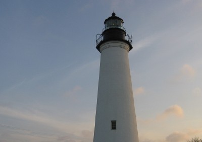
It appears to me that if one wants to make progress in mathematics, one should study the masters and not the pupils. - Niels Henrik Abel.
Nothing is better than reading and gaining more and more knowledge - Stephen William Hawking.
Offline
#508 2019-09-23 00:08:06
- Jai Ganesh
- Administrator
- Registered: 2005-06-28
- Posts: 53,626
Re: Miscellany
409) Water Table
The water table is an underground boundary between the soil surface and the area where groundwater saturates spaces between sediments and cracks in rock. Water pressure and atmospheric pressure are equal at this boundary.
The soil surface above the water table is called the unsaturated zone, where both oxygen and water fill the spaces between sediments. The unsaturated zone is also called the zone of aeration due to the presence of oxygen in the soil. Underneath the water table is the saturated zone, where water fills all spaces between sediments. The saturated zone is bounded at the bottom by impenetrable rock.
The shape and height of the water table is influenced by the land surface that lies above it; it curves up under hills and drops under valleys. The groundwater found below the water table comes from precipitation that has seeped through surface soil. Springs are formed where the water table naturally meets the land surface, causing groundwater to flow from the surface and eventually into a stream, river, or lake.
The water table level can vary in different areas and even within the same area. Fluctuations in the water table level are caused by changes in precipitation between seasons and years. During late winter and spring, when snow melts and precipitation is high, the water table rises. There is a lag, however, between when precipitation infiltrates the saturated zone and when the water table rises. This is because it takes time for water to trickle through spaces between sediments to reach the saturated zone, although the process is helped by gravity. Irrigation of crops can also cause the water table to rise as excess water seeps into the ground.
During the summer months, the water table tends to fall, due in part to plants taking up water from the soil surface before it can reach the water table. The water table level is also influenced by human extraction of groundwater using wells; groundwater is pumped out for drinking water and to irrigate farmland. The depth of the water table can be measured in existing wells to determine the effects of season, climate, or human impact on groundwater. The water table can actually be mapped across regions using measurements taken from wells.
If water is not extracted through a well in a sustainable manner, the water table may drop permanently. This is starting to be the case around the world. Some of the largest sources of groundwater are being depleted in India, China, and the United States to the point where they cannot be replenished. Groundwater depletion occurs when the rate of groundwater extraction through wells is higher than the rate of replenishment from precipitation.
It appears to me that if one wants to make progress in mathematics, one should study the masters and not the pupils. - Niels Henrik Abel.
Nothing is better than reading and gaining more and more knowledge - Stephen William Hawking.
Offline
#509 2019-09-25 00:49:03
- Jai Ganesh
- Administrator
- Registered: 2005-06-28
- Posts: 53,626
Re: Miscellany
410) Diesel Fuel
Diesel fuel, also called diesel oil, combustible liquid used as fuel for diesel engines, ordinarily obtained from fractions of crude oil that are less volatile than the fractions used in gasoline. In diesel engines the fuel is ignited not by a spark, as in gasoline engines, but by the heat of air compressed in the cylinder, with the fuel injected in a spray into the hot compressed air. Diesel fuel releases more energy on combustion than equal volumes of gasoline, so diesel engines generally produce better fuel economy than gasoline engines. In addition, the production of diesel fuel requires fewer refining steps than gasoline, so retail prices of diesel fuel traditionally have been lower than those of gasoline (depending on the location, season, and taxes and regulations). On the other hand, diesel fuel, at least as traditionally formulated, produces greater quantities of certain air pollutants such as sulfur and solid carbon particulates, and the extra refining steps and emission-control mechanisms put into place to reduce those emissions can act to reduce the price advantages of diesel over gasoline. In addition, diesel fuel emits more carbon dioxide per unit than gasoline, offsetting some of its efficiency benefits with its greenhouse gas emissions.
Several grades of diesel fuel are manufactured—for example, “light-middle” and “middle” distillates for high-speed engines with frequent and wide variations in load and speed (such as trucks and automobiles) and “heavy” distillates for low- and medium-speed engines with sustained loads and speeds (such as trains, ships, and stationary engines). Performance criteria are cetane number (a measure of ease of ignition), ease of volatilization, and sulfur content. The highest grades, for automobile and truck engines, are the most volatile, and the lowest grades, for low-speed engines, are the least volatile, leave the most carbon residue, and commonly have the highest sulfur content.
Sulfur is a critical polluting component of diesel and has been the object of much regulation. Traditional “regular” grades of diesel fuel contained as much as 5,000 parts per million (ppm) by weight sulfur. In the 1990s “low sulfur” grades containing no more than 500 ppm sulfur were introduced, and in the following years even lower levels of sulfur were required.
Regulations in the United States required that by 2010 diesel fuels sold for highway vehicles be “ultra-low sulfur” (ULSD) grades, containing a maximum of 15 ppm. In the European Union, regulations required that from 2009 diesel fuel sold for road vehicles be only so-called “zero-sulfur,” or “sulfur-free,” diesels, containing no more than 10 ppm. Lower sulfur content reduces emissions of sulfur compounds implicated in acid rain and allows diesel vehicles to be equipped with highly effective emission-control systems that would otherwise be damaged by higher concentrations of sulfur. Heavier grades of diesel fuel, made for use by off-road vehicles, ships and boats, and stationary engines, are generally allowed higher sulfur content, though the trend has been to reduce limits in those grades as well.
In addition to traditional diesel fuel refined from petroleum, it is possible to produce so-called synthetic diesel, or Fischer-Tropsch diesel, from natural gas, from synthesis gas derived from coal, or from biogas obtained from biomass. Also, biodiesel, a biofuel, can be made primarily from oily plants such as the soybean or oil palm. These alternative diesel fuels can be blended with traditional diesel fuel or used alone in diesel engines without modification, and they have very low sulfur content. Alternative diesel fuels are often proposed as means to reduce dependence on petroleum and to reduce overall emissions, though only biodiesel can provide a life cycle carbon dioxide benefit.

It appears to me that if one wants to make progress in mathematics, one should study the masters and not the pupils. - Niels Henrik Abel.
Nothing is better than reading and gaining more and more knowledge - Stephen William Hawking.
Offline
#510 2019-09-27 00:25:45
- Jai Ganesh
- Administrator
- Registered: 2005-06-28
- Posts: 53,626
Re: Miscellany
411) Elevator
An elevator is an enclosed car that moves in a vertical shaft between the multi-story floors of a building carrying passengers or freight. In England, it is called a lift. All elevators are based on the principle of the counterweight. Modern elevators also use geared, electric motors and a system of cables and pulleys to propel them. It is the world’s most often used means of mechanical transportation, and it is also the safest. The elevator has played a crucial role in the development of the high-rise or skyscraper. It is largely responsible for how cities look today. Sometimes also called vertical transport systems in the elevator industry, it has become an indispensable factor of modern urban life.
History
Lifting loads by mechanical means goes back at least to the Romans who used primitive hoists operated by human, animal, or water power during their ambitious building projects. An elevator employing a counterweight is said to have been built in the seventeenth century by a Frenchman named Velayer. It was also in that country that a passenger elevator was built in 1743 at the Versailles Palace for King Louis XV. By 1800, steam power was used to power such lift devices, and in 1830, several European factories were operating with hydraulic elevators that were pushed up and down by a plunger that worked in and out of a cylinder.
All of these lifting systems were based on the principle of the counterweight, by which the weight of one object is used to balance the weight of another object. For example, while it may be very difficult to pull up a heavy object using only a rope tied to it, this job can be made very easy if a weight is attached to the other end of the rope and hung over a pulley. This other weight, or counterweight, balances the first and makes it easy to pull up. Thus, an elevator, which uses the counterweight system, never has to pull up the total weight of its load, but only the difference between the load-weight and that of the counter-weight. Counterweights are also found inside the sash of old-style windows, in grandfather clocks, and in dumbwaiters.
Until the mid-nineteenth century, the prevailing elevator systems had two problems. The plunger system was very safe but also extremely slow, and it had obvious height limitations. If the plunger system was scrapped and the elevator car was hung from a rope to achieve higher speeds, the risk of the rope or cable breaking was an ever-present and very real danger. Safety was the main technical problem that American inventor Elisha Graves Otis (1811–1861) solved when he invented the first modern, fail-safe passenger elevator in 1853. In that year, Otis demonstrated his fail-safe mechanism at the Crystal Palace Exposition in London, England. In front of an astonished audience, he rode his invention high above the crowd and ordered that the cable holding the car be severed. When it was, instead of crashing to the ground, his fail-safe mechanism worked automatically and stopped the car.
The secret of Otis’s success was a bow-shaped wagon spring device that would flex and jam its ends into the guide rails if tension on the rope or cable was released. What he had invented was a type of speed governor that translated an elevator’s downward motion into a sideways, braking action. On March 23, 1857, Otis installed the first commercial passenger elevator in the Haughwout Department Store (488 Broadway) in New York City, and the age of the skyscraper was begun. Until then, large city buildings were limited to five or six stories, which was the maximum number of stairs people were willing to climb. When architects developed the iron-frame building in the 1880s, the elevator was ready to service them. By then, electric power had replaced the old steam-driven elevator. German inventor Ernest Werner von Siemens (1816–1892) built the first electric elevator in 1880. The first commercial passenger elevator to be powered by electricity was installed in 1889 in the Desmarest Building in New York City. In 1904, a gearless feature was added to the electric motor, making elevator speed virtually limitless. By 1915, automatic leveling had been introduced and cars would now stop precisely where they should.
Key Terms
Centrifugal force— The inertial reaction that causes a body to move away from a center about which it revolves.
Counterweight— The principle in which the weight of one object is used to balance the weight of another object; for an elevator, it is a weight that counterbalances the weight of the elevator car plus approximately 40% of its capacity load.
Hydraulic elevator— A power elevator where the energy is applied, by means of a liquid under pressure, in a cylinder equipped with a plunger or a piston; a direct-plunge elevator had the elevator car attached directly to the plunger or piston that went up and down a sunken shaft.
Microprocessor— The central processing unit of a microcomputer that contains the silicon chip, which decodes instructions and controls operations.
Sheave— A wheel mounted in bearings and having one or more grooves over which a rope or ropes may pass.
Speed governor— A device that mechanically regulates the speed of a machine, preventing it from going any faster than a preset velocity.
Modern elevators
Today’s passenger elevators are not fundamentally different from the Otis original. Practically all are electrically propelled and are lifted between two guide rails by steel cables that loop over a pulley device called a sheave at the top of the elevator shaft. They still employ the counterweight principle. The safety mechanism, called the overspeed governor, is an improved version of the Otis original. It uses centrifugal force that causes a system of weights to swing outward toward the rails should the car’s speed exceed a certain limit. Although the travel system has changed little, its control system has been revolutionized. Speed and automation now characterize elevators, with microprocessors gradually replacing older electromechanical control systems. Speeds ranging up to 1, 800 ft (550 m) per minute can be attained. Separate outer and inner doors are another essential safety feature, and most now have electrical sensors that pull the doors open if they sense something between them. Most elevators also have telephones, alarm buttons, and emergency lighting. Escape hatches in their roofs serve both for maintenance and for emergency use.
Modern elevators can also be programmed to provide the fastest possible service with a minimum number of cars. They can further be set to sense the weight of a car and to bypass all landing calls when fully loaded. In addition to regular passenger or freight elevators, today’s specialized lifts are used in ships, dams, and even on rocket launch pads. Today’s elevators are safe, efficient, and an essential part of daily lives.
In 2006, the Otis Elevator Company is part of United Technologies Corporation. It is the largest manufacturer of elevators. Other manufacturers of elevators are Thyssen-Krupp, Kone, and Schindler.

It appears to me that if one wants to make progress in mathematics, one should study the masters and not the pupils. - Niels Henrik Abel.
Nothing is better than reading and gaining more and more knowledge - Stephen William Hawking.
Offline
#511 2019-10-01 00:41:14
- Jai Ganesh
- Administrator
- Registered: 2005-06-28
- Posts: 53,626
Re: Miscellany
412) Mensa International
Mensa is the largest and oldest high IQ society in the world. It is a non-profit organization open to people who score at the 98th percentile or higher on a standardised, supervised IQ or other approved intelligence test. Mensa formally comprises national groups and the umbrella organisation Mensa International, with a registered office in Caythorpe, Lincolnshire, England] (which is separate from the British Mensa office in Wolverhampton). The word mensa is Latin for "table", as is symbolised in the organisation's logo, and was chosen to demonstrate the round-table nature of the organisation; the coming together of equals.
History
Roland Berrill, an Australian barrister, and Dr. Lancelot Ware, a British scientist and lawyer, founded Mensa at Lincoln College, in Oxford, England, in 1946. They had the idea of forming a society for very intelligent people, the only qualification for membership being a high IQ. It was ostensibly to be non-political and free from all other social distinctions (racial, religious, etc.).
However, Berrill and Ware were both disappointed with the resulting society. Berrill had intended Mensa as "an aristocracy of the intellect", and was unhappy that a majority of Mensans came from humble homes, while Ware said: "I do get disappointed that so many members spend so much time solving puzzles."
American Mensa was the second major branch of Mensa. Its success has been linked to the efforts of early and longstanding organiser Margot Seitelman.
Membership requirement
Mensa's requirement for membership is a score at or above the 98th percentile on certain standardised IQ or other approved intelligence tests, such as the Stanford–Binet Intelligence Scales. The minimum accepted score on the Stanford–Binet is 132, while for the Cattell it is 148. Most IQ tests are designed to yield a mean score of 100 with a standard deviation of 15; the 98th-percentile score under these conditions is 131, assuming a normal distribution.
Most national groups test using well established IQ test batteries, but American Mensa has developed its own application exam. This exam is proctored by American Mensa and does not provide a score comparable to scores on other tests; it serves only to qualify a person for membership. In some national groups, a person may take a Mensa-offered test only once, although one may later submit an application with results from a different qualifying test. The Mensa test is also available in developing countries like India, Pakistan, etc. and societies in developing countries have been growing at rapid pace.
Mission
Mensa's constitution lists three purposes: "to identify and to foster human intelligence for the benefit of humanity; to encourage research into the nature, characteristics, and uses of intelligence; and to provide a stimulating intellectual and social environment for its members".
To these ends, the organisation is involved with programs for gifted children, literacy, and scholarships, and it holds numerous gatherings including an annual summit.
Presidents
• 2013-2015: Elissa Rudolph
• 2015-2019: Bibiána Balanyi
• 2019-present: Bjorn Liljeqvist
Organisational structure
Mensa International consists of around 134,000 members, in 100 countries, in 51 national groups. The national groups issue periodicals, such as Mensa Bulletin, the monthly publication of American Mensa, and Mensa Magazine, the monthly publication of British Mensa. Individuals who live in a country with a national group join the national group, while those living in countries without a recognised chapter may join Mensa International directly.
The largest national groups are:
• American Mensa, with more than 57,000 members,
• British Mensa, with over 21,000 members, and
• Mensa Germany, with more than 13,000 members.
Larger national groups are further subdivided into local groups. For example, American Mensa has 134 local groups, with the largest having over 2,000 members and the smallest having fewer than 100.
Members may form Special Interest Groups (SIGs) at international, national, and local levels; these SIGs represent a wide variety of interests, ranging from motorcycle clubs to entrepreneurial co-operations. Some SIGs are associated with various geographic groups, whereas others act independently of official hierarchy. There are also electronic SIGs (eSIGs), which operate primarily as e-mail lists, where members may or may not meet each other in person.
The Mensa Foundation, a separate charitable U.S. corporation, edits and publishes its own Mensa Research Journal, in which both Mensans and non-Mensans are published on various topics surrounding the concept and measure of intelligence.
Gatherings
Mensa has many events for members, from the local to the international level. Several countries hold a large event called the Annual Gathering (AG). It is held in a different city every year, with speakers, dances, leadership workshops, children's events, games, and other activities. The American and Canadian AGs are usually held during the American Independence Day (4 July) or Canada Day (1 July) weekends respectively.
Smaller gatherings called Regional Gatherings (RGs), which are held in various cities, attract members from large areas. The largest in the United States is held in the Chicago area around Halloween, notably featuring a costume party for which many members create pun-based costumes.
In 2006, the Mensa World Gathering was held from 8–13 August in Orlando, Florida to celebrate the 60th anniversary of the founding of Mensa. An estimated 2,500 attendees from over 30 countries gathered for this celebration. The International Board of Directors had a formal meeting there.
In 2010, a joint American-Canadian Annual Gathering was held in Dearborn, Michigan, to mark the 50th anniversary of Mensa in North America, one of several times the US and Canada AGs have been combined. Other multinational gatherings are the European Mensas Annual Gathering (EMAG) and the Asian Mensa Gathering (AMG).]
Since 1990, American Mensa has sponsored the annual Mensa Mind Games competition, at which the Mensa Select award is given to five board games that are "original, challenging, and well designed".
Individual local groups and their members host smaller events for members and their guests. Lunch or dinner events, lectures, tours, theatre outings, and games nights are all common.
In Europe since 2008 international meetings have been held under the name [EMAG] (European Mensa Annual Gathering), starting in Cologne in 2008. Next editions were in Utrecht (2009), Prague (2010), Paris (2011), Stockholm (2012), Bratislava (2013), Zürich (2014), Berlin (2015), Kraków (2016), Barcelona (2017), Belgrade (2018) and Ghent (2019). The 2020 edition will take place in Brno, from July 29 to August 2. The gathering for 2021 is planned for Århus.
In Asia there is an Asian Mensa Gathering (AMG) with rotating countries hosting the event.
Publications
All Mensa groups publish members-only newsletters or magazines, which include articles and columns written by members, and information about upcoming Mensa events. Examples include the American Mensa Bulletin, the British Mensa magazine, Serbian MozaIQ. the Australian TableAus, the Mexican El Mensajero, and the French Contacts. Some local or regional groups have their own newsletter, such as those in the United States, UK, Germany, and France.
Mensa International publishes a Mensa World Journal, which "contains views and information about Mensa around the world". This journal is generally included in each national magazine.
Mensa also publishes the Mensa Research Journal, which "highlights scholarly articles and recent research related to intelligence". Unlike most Mensa publications, this journal is available to non-members.
Demographics
All national and local groups welcome children; many offer activities, resources, and newsletters specifically geared toward gifted children and their parents. Both American Mensa's youngest member (Christina Brown) and British Mensa's youngest member (Adam Kirby) joined at the age of two. The current youngest member of Mensa is Adam Kirby, from Mitcham, London, UK who was invited to join at the age of two years and four months and gained full membership at the age of two years five months. He scored 141 on the Stanford-Binet IQ test. Elise Tan-Roberts of the UK is the youngest person ever to join Mensa, having gained full membership at the age of two years and four months.
American Mensa's oldest member is 102, and British Mensa had a member aged 103.
According to American Mensa's website (as of 2013), 38 percent of its members are baby boomers between the ages of 51 and 68, 31 percent are Gen-Xers or Millennials between the ages of 27 and 48, and more than 2,600 members are under the age of 18. There are more than 1,800 families in the United States with two or more Mensa members. In addition, the American Mensa general membership is "66 percent male, 34 percent female". The aggregate of local and national leadership is distributed equally between the genders.

It appears to me that if one wants to make progress in mathematics, one should study the masters and not the pupils. - Niels Henrik Abel.
Nothing is better than reading and gaining more and more knowledge - Stephen William Hawking.
Offline
#512 2019-10-03 00:15:00
- Jai Ganesh
- Administrator
- Registered: 2005-06-28
- Posts: 53,626
Re: Miscellany
413) Telescope
The telescope is an instrument that collects and analyzes the radiation emitted by distant sources. The most common type is the optical telescope, a collection of lenses and/or mirrors that is used to allow the viewer to see distant objects more clearly by magnifying them or to increase the effective brightness of a faint object. In a broader sense, telescopes can operate at most frequencies of the electromagnetic spectrum, from radio waves to gamma rays. The one characteristic all telescopes have in common is the ability to make distant objects appear to be closer. The word telescope is derived from the Greek tele meaning far, and skopein meaning to view.
The first optical telescope was probably constructed by German-born Dutch lensmaker Hans Lippershey (1570–1619), in 1608. The following year, Italian astronomer and physicist Galileo Galilei (1564– 1642) built the first astronomical telescope, from a tube containing two lenses of different focal lengths aligned on a single axis (the elements of this telescope are still on display in Florence, Italy). With this telescope and several following versions, Galileo made the first telescopic observations of the sky and discovered lunar mountains, four of Jupiter’s moons, sunspots, and the starry nature of the Milky Way galaxy. Since then, telescopes have increased in size and improved in image quality. Computers are now used to aid in the design of large, complex telescope systems.
Operation Of A Telescope
Light gathering
The primary function of a telescope is that of radiation gathering, in many cases light gathering. As will be seen below, resolution limits on telescopes would not call for an aperture much larger than about 30 in (76 cm). However, there are many telescopes around the world with diameters several times this value. The reason for this occurrence is that larger telescopes can see further because they can collect more light. The 200 in (508 cm) diameter reflecting telescope at Mt. Palomar, California, for instance can gather 25 times more light than the 40 in (102 cm) Yerkes telescope at Williams Bay, Wisconsin, the largest refracting telescope in the world. The light gathering power grows as the area of the objective increases, or the square of its diameter if it is circular. The more light a telescope can gather, the more distant the objects it can detect, and therefore larger telescopes increase the size of the observable universe.
Resolution
The resolution, or resolving power, of a telescope is defined as being the minimum angular separation between two different objects that can be detected.
Unfortunately, astronomers are not able to increase the resolution of a telescope simply by increasing the size of the light gathering aperture to as large a size as is need. Disturbances and non-uniformities in the atmosphere limit the resolution of telescopes positioned on the surface of Earth to somewhere in the range 0.5 to 2 arc seconds, depending on the location of the telescope. Telescope sights on top of mountains are popular since the light reaching the instrument has to travel through less air, and consequently the image has a higher resolution. However, a limit of 0.5 arc seconds corresponds to an aperture of only 12 in (30 cm) for visible light: larger telescopes do not provide increased resolution but only gather more light.
Magnification
Magnification is not the most important characteristic of telescopes as is commonly thought. The magnifying power of a telescope is dependent on the type and quality of eyepiece being used. The magnification is given simply by the ratio of the focal lengths of the objective and eyepiece. Thus, a 0.8 in (2 cm) focal length eyepiece used in conjunction with a 39 in (100 cm) focal length objective will give a magnification of 50. If the field of view of the eyepiece is 20°, the true field of view will be 0.4°.
Types Of Telescope
Most large telescopes built before the twentieth century were refracting telescopes because techniques were readily available to polish lenses. Not until the latter part of the nineteenth century were techniques developed to coat large mirrors, which allowed the construction of large reflecting telescopes.
Refracting telescopes
The parallel light from a distant object enters the objective, of focal length f1, from the left. The light then comes to a focus at a distance f1 from the objective. The eyepiece, with focal length f2, is situated a distance f1+ f2 from the objective such that the light exiting the eyepiece is parallel. Light coming from a second object (dashed lines) exits the eyepiece at an angle equal to f1/f2 times the angle of the light entering.
Refracting telescopes, i.e., telescopes that use lenses, can suffer from problems of chromatic and other aberrations, which reduce the quality of the image. In order to correct for these, multiple lenses are required, much like the multiple lens systems in a camera lens unit. The advantages of the refracting telescope include having no central stop or other diffracting element in the path of light as it enters the telescope, and the stability of the alignment and transmission characteristics over long periods of time. However, the refracting telescope can have low overall transmission due to reflection at the surface of all the optical elements. In addition, the largest refractor ever built has a diameter of only 40 in (102 cm): lenses of a larger diameter will tend to distort under their own weight and give a poor image. Additionally, each lens needs to have both sides polished perfectly and be made from material that is of highly uniform optical quality throughout its entire volume.
Reflecting telescopes
All large telescopes, both existing and planned, are of the reflecting variety. Reflecting telescopes have several advantages over refracting designs. First, the reflecting material (usually aluminum), deposited on a polished surface, has no chromatic aberration. Second, the whole system can be kept relatively short by folding the light path, as shown in the Newtonian and Cassegrain designs below. Third, the objectives can be made very large, since there is only one optical surface to be polished to high tolerance, the optical quality of the mirror substrate is unimportant and the mirror can be supported from the back to prevent bending. The disadvantages of reflecting systems are 1) alignment is more critical than in refracting systems, resulting in the use of complex adjustments for aligning the mirrors and the use of temperature insensitive mirror substrates and 2) the secondary or other auxiliary mirrors are mounted on a support structure that occludes part of the primary mirror and causes diffraction.
These are a) the prime focus, where the detector is simply placed at the prime focus of the mirror; b) the Newtonian, where a small, flat mirror reflects the light out to the side of the telescope; c) the Cassegrain, where the focus is located behind the plane of the primary mirror through a hole in its center and d) the Coudè, where the two flat mirrors provide a long focal length path as shown.
Catadioptric telescopes
Catadioptric telescopes use a combination of lenses and mirrors in order to obtain some of the advantages of both. The best-known type of catadioptric is the Schmidt telescope or camera, which is usually used to image a wide field of view for large area searches. The lens in this system is very weak and is commonly referred to as a corrector-plate.
Overcoming Resolution Limitations
The limits to the resolution of a telescope are, as described above, a result of the passage of the light from the distant body through the atmosphere, which is optically non-uniform. Stars appear to twinkle because of constantly fluctuating optical paths through the atmosphere, which results in a variation in both brightness and apparent position. Consequently, much information is lost to astronomers simply because they do not have sufficient resolution from their measurements. There are three ways of overcoming this limitation, namely setting the telescope out in space in order to avoid the atmosphere altogether, compensating for the distortion on a ground-based telescope, and/or stellar interferometry. The first two methods are innovations of the 1990s and have lead to a new era in observational astronomy.
Space Telescopes
The best known and biggest orbiting optical telescope is the Hubble Space Telescope (HST), which has an 8 ft (2.4 m) primary mirror and five major instruments for examining various characteristics of distant bodies. After a much-publicized problem with the focusing of the telescope and the installation of a package of corrective optics in 1993, the HST has proved to be the finest of all telescopes ever produced. The data collected from HST is of such a high quality that researchers can solve problems that have been in question for years, often with a single photograph. The resolution of the HST is 0.02 arc seconds, close to the theoretical limit since there is no atmospheric distortion, and a factor of around twenty times better than was previously possible. An example of the significant improvement in imaging that space-based systems have given is the Doradus 30 nebula, which prior to the HST was thought to have consisted of a small number of very bright stars. In a photograph taken by the HST it now appears that the central region has over 3,000 stars.
Another advantage of using a telescope in orbit about Earth is that the telescope can detect wavelengths such as the ultraviolet and various portions of the infrared, which are absorbed by the atmosphere and not detectable by ground-based telescopes.
Adaptive Optics
In 1991, the United States government declassified adaptive optics systems (systems that remove atmospheric effects), which had been developed under the Strategic Defense Initiative for ensuring that a laser beam could penetrate the atmosphere without significant distortion.
A laser beam is transmitted from the telescope into a layer of mesospheric sodium at 56–62 mi (90– 100 km) altitude. The laser beam is resonantly backscattered from the volume of excited sodium atoms and acts as a guide-star whose position and shape are well defined except for the atmospheric distortion. The telescope collects the light from the guide-star and a wavefront sensor determines the distortion caused by the atmosphere. This information is then fed back to a deformable mirror, or an array of many small mirrors, which compensates for the distortion. As a result, stars that are located close to the guide-star come into a focus, which is many times better than can be achieved without compensation. Telescopes have operated at the theoretical resolution limit for infrared wavelengths and have shown an improvement in the visible region of more than ten times. Atmospheric distortions are constantly changing, so the deformable mirror has to be updated every five milliseconds, which is easily achieved with modern computer technology.
Recording Telescope Data
Telescopes collect light largely for two types of analysis, imaging and spectrometry. The better known is imaging, the goal of which is simply to produce an accurate picture of the objects that are being examined. In past years, the only means of recording an image was to take a photograph. For long exposure times, the telescope had to track the sky by rotating at the same speed as the Earth, but in the opposite direction. This is still the case today, but the modern telescope no longer uses photographic film but a charge-coupled device (CCD) array. The CCD is a semiconductor light detector, which is fifty times more sensitive than photographic film, and is able to detect single photons. Being fabricated using semiconductor techniques, the CCD can be made to be very small, and an array typically has a spacing of 15 microns between CCD pixels. A typical array for imaging in telescopes will have a few million pixels. There are many advantages of using the CCD over photographic film or plates, including the lack of a developing stage and the output from the CCD can be read directly into a computer and the data analyzed and manipulated with relative ease.
The second type of analysis is spectrometry, which means that the researcher wants to know what wavelengths of light are being emitted by a particular object. The reason behind this is that different atoms and molecules emit different wavelengths of light—measuring the spectrum of light emitted by an object can yield information as to its constituents. When performing spectrometry, the output of the telescope is directed to a spectrometer, which is usually an instrument containing a diffraction grating for separating the wavelengths of light. The diffracted light at the output is commonly detected by a CCD array and the data read into a computer.
Modern Optical Telescopes
For almost 40 years the Hale telescope at Mt. Palomar (San Diego, California) was the world’s largest with a primary mirror diameter of 200 in (5.1 m). During that time, improvements were made primarily in detection techniques, which reached fundamental limits of sensitivity in the late 1980s. In order to observe fainter objects, it became imperative to build larger telescopes, and so a new generation of telescopes is being developed for the 2000s and beyond. These telescopes use revolutionary designs in order to increase the collecting area; 2,260 square feet (210 square meters) is being used for the European Southern Observatory (ESO), which operates observatories in Chile; the organization is headquartered near Munich, Germany.
This new generation of telescopes does not use the solid, heavy primary mirror of previous designs, whose thickness was between one-sixth and one-eighth of the mirror diameter. Instead, it uses a variety of approaches to reduce the mirror weight and improve its thermal and mechanical stability, including using many hexagonal mirror elements forming a coherent array; a single large meniscus mirror (with a thickness one-fortieth of the diameter), with many active support points which bend the mirror into the correct shape; and, a single large mirror formed from a honeycomb sandwich. In 2005, one of the first pictures taken by ESO was of 2M1207b, an exo-solar planet (a planet orbiting a star other than the sun) orbiting a brown dwarf star about 260 light-years away (where one light-year is the distance that light travels in vacuum in one year). These new telescopes, combined with quantum-limited detectors, distortion reduction techniques, and coherent array operation allow astronomers to see objects more distant than have been observed before.
One of this new generation, the Keck telescope located on Mauna Kea in Hawaii, is currently the largest operating optical/infrared telescope, using a 32 ft (10 m) effective diameter hyperbolic primary mirror constructed from 36 6-ft (1.8-m) hexagonal mirrors. The mirrors are held to relative positions of less than 50 nm using active sensors and actuators in order to maintain a clear image at the detector.
Because of its location at over 14,000 ft (4,270 m), the Keck is useful for collecting light over the range of 300 nm to 30 æm. In the late 1990s, Keck I was joined by an identical twin, Keck II. Then, in 2001, the two telescopes were linked together through the use of interferometry for an effective mirror diameter of 279 ft (85 m).
Alternative Wavelengths
Most of the discussion so far has been concerned with optical telescopes operating in the range from 300 to 1,100 nanometers (nm). However, valuable information is contained in the radiation reaching Earth at different wavelengths and telescopes have been built to cover wide ranges of operation, including radio and millimeter waves, infrared, ultraviolet, x rays, and gamma rays.
Infrared telescopes
Infrared telescopes are particularly useful for examining the emissions from gas clouds. Since water vapor in the atmosphere can absorb some of this radiation, it is especially important to locate infrared telescopes in high altitudes or in space. In 1983, NASA launched the highly successful Infrared Astronomical Satellite, which performed an all-sky survey, revealing a wide variety of sources and opening up new avenues of astrophysical discovery. With the improvement in infrared detection technology in the 1980s, the 1990s saw several new infrared telescopes, including the Infrared Optimized Telescope, a 26 ft (8 m) diameter facility, on Mauna Kea, Hawaii. In August 2003, NASA launched the Spitzer Space Telescope (formerly the Space Infrared Telescope Facility; named after Lyman Spitzer, Jr., who first suggested placing telescopes in orbit in the 1940s). It is in orbit about the sun (a heliocentric orbit), in which it follows behind Earth’s orbit about the sun, slowly receding away from Earth each year. Its primary mirror is about 2.8 ft (85 cm) in diameter, with a focal length that is twelve times the diameter of the primary mirror.
Several methods are used to reduce the large thermal background that makes viewing infrared difficult, including the use of cooled detectors and dithering the secondary mirror. This latter technique involves pointing the secondary mirror alternatively at the object in question and then at a patch of empty sky. Subtracting the second signal from the first results in the removal of most of the background thermal (infrared) noise received from the sky and the telescope itself, thus allowing the construction of a clear signal.
Radio telescopes
Radio astronomy was developed following World War II, using the recently developed radio technology to look at radio emissions from the sky. The first radio telescopes were very simple, using an array of wires as the antenna. In the 1950s, the now familiar collecting dish was introduced and has been widely used ever since.
Radio waves are not susceptible to atmospheric disturbances like optical waves are, and so the development of radio telescopes over the past forty years has seen a continued improvement in both the detection of faint sources as well as in resolution. Despite the fact that radio waves can have wavelengths which are meters long, the resolution achieved has been to the sub-arc second level through the use of many radio telescopes working together in an interferometer array, the largest of which stretches from Hawaii to the United States Virgin Islands (known as the Very Long Baseline Array). The largest working radio telescope is the Giant Meterwave Radio Telescope in India. It contains 14 telescopes arranged around a central square and another 16 positioned within three arms of a Y-shaped array. Its total interferometric baseline is about 15.5 mi (25 km). Construction is being made on the Low Frequency Array (LOFAR), which is a series of radio telescopes located across the Netherlands and Germany. As of September 2006, LOFAR has been constructed and is in the testing stage. When operational, it will have a total collecting area of around 0.4
KEY TERMS
Chromatic aberration —The reduction in image quality arising from the fact that the refractive index in varies across the spectrum.
Objective —The large light collecting lens used in a refracting telescope.
Reflecting telescope —A telescope that uses only reflecting elements, i.e., mirrors.
Refracting telescope —A telescope that uses only refracting elements; i.e., lenses.
Spectrometry —The measurement of the relative strengths of different wavelength components that make up a light signal.
It appears to me that if one wants to make progress in mathematics, one should study the masters and not the pupils. - Niels Henrik Abel.
Nothing is better than reading and gaining more and more knowledge - Stephen William Hawking.
Offline
#513 2019-10-05 00:45:37
- Jai Ganesh
- Administrator
- Registered: 2005-06-28
- Posts: 53,626
Re: Miscellany
414) Differences in Microphones & Speakers
Although at first glance, microphones and speakers appear to be very different kinds of devices, they are in fact closely related. Speakers and microphones are both transducers -- components which transform energy from one type to another. A speaker turns electrical currents into sound waves; a microphone converts sound into electrical energy. The main differences between them lie in the way audio designers have optimized each to perform its particular task efficiently.
Speaker
A speaker produces sound when you drive it with an amplifier connected to an audio source. Most speakers use a electromagnet design in which a permanent magnet is situated in a metal frame that holds a cone made of paper or plastic. A wire coil attached to the end of the cone produces attractive and repulsive forces when electrical current flows through it; the pushing and pulling against the cone generates sound waves. The cone's size dictates the general frequency range it reproduces most efficiently: large cones produce low frequencies, and small ones generate high frequencies.
Microphone
When you speak or sing into a microphone, the sound waves of your voice produce vibrations in a diaphragm inside the mike. Although they have a variety of basic designs, a common type called the dynamic microphone uses a magnetic principle similar to that used in speakers. The diaphragm carries a lightweight wire coil made of fine wire; the coil moves through a magnetic field and produces electrical currents which mirror the incoming sound waves. Another popular design, called the condenser microphone, places the diaphragm on one of two metal plates separated by an insulator. The vibrations in the diaphragm produce changes in the electrical capacitance between the two plates. Condenser mics require a battery, as the capacitance effect doesn't produce electrical currents by itself.
Similarities
The dynamic microphone and standard speaker both employ a moving coil in a magnetic field, producing electrical currents from sound vibrations or vice-versa. It is possible, although risky, to connect a dynamic microphone to a speaker output and hear sound from the mic. As the microphone is not designed to handle electrical inputs, a loud amp setting can destroy the mic if used in this manner. In the same way, you can connect a speaker to a microphone input, but because a speaker doesn't make an ideal mike, you must yell into it to produce a detectable signal. Walkie-talkies and room intercom systems use a single speaker-microphone device that performs both functions moderately well.
Differences
Microphones produce a relatively weak output that requires preamplification to bring the signal to a standard line level. Because the signals are weak, microphone cables have shielding that reduces electrical noise picked up from fluorescent lights and appliances. A microphone picks up a wide range of frequencies with great sensitivity. The loudspeaker's purpose is to fill a room with high-fidelity sound. This means handling large amounts of power from an amplifier -- up to several hundred watts for some types of speakers. To manage the power, the speaker has a robust, heavy design. For good fidelity, a single speaker cabinet may have two or more separate speaker drivers, each suited to a particular frequency range; a single speaker does not have the wide range that a microphone has.

It appears to me that if one wants to make progress in mathematics, one should study the masters and not the pupils. - Niels Henrik Abel.
Nothing is better than reading and gaining more and more knowledge - Stephen William Hawking.
Offline
#514 2019-10-10 00:03:57
- Jai Ganesh
- Administrator
- Registered: 2005-06-28
- Posts: 53,626
Re: Miscellany
415) Gyroscope
Gyroscope, device containing a rapidly spinning wheel or circulating beam of light that is used to detect the deviation of an object from its desired orientation. Gyroscopes are used in compasses and automatic pilots on ships and aircraft, in the steering mechanisms of torpedoes, and in the inertial guidance systems installed in space launch vehicles, ballistic missiles, and orbiting satellites.
Mechanical Gyroscopes
Mechanical gyroscopes are based on a principle discovered in the 19th century by Jean-Bernard-Léon Foucault, a French physicist who gave the name gyroscope to a wheel, or rotor, mounted in gimbal rings. The angular momentum of the spinning rotor caused it to maintain its attitude even when the gimbal assembly was tilted. During the 1850s Foucault conducted an experiment using such a rotor and demonstrated that the spinning wheel maintained its original orientation in space regardless of Earth’s rotation. This ability suggested a number of applications for the gyroscope as a direction indicator, and in 1908 the first workable gyrocompass was developed by German inventor H. Anschütz-Kaempfe for use in a submersible. In 1909 American inventor Elmer A. Sperry built the first automatic pilot using a gyroscope to maintain an aircraft on course. The first automatic pilot for ships was installed in a Danish passenger ship by a German company in 1916, and in that same year a gyroscope was used in the design of the first artificial horizon for aircraft.
Gyroscopes have been used for automatic steering and to correct turn and pitch motion in cruise and ballistic missiles since the German V-1 missile and V-2 missile of World War II. Also during that war, the ability of gyroscopes to define direction with a great degree of accuracy, used in conjunction with sophisticated control mechanisms, led to the development of stabilized gunsights, bombsights, and platforms to carry guns and radar antennas aboard ships. The inertial guidance systems used by orbital spacecraft require a small platform that is stabilized to an extraordinary degree of precision; this is still done by traditional gyroscopes. Larger and heavier devices called momentum wheels (or reaction wheels) also are used in the attitude control systems of some satellites.
Optical Gyroscopes
Optical gyroscopes, with virtually no moving parts, are used in commercial jetliners, booster rockets, and orbiting satellites. Such devices are based on the Sagnac effect, first demonstrated by French scientist Georges Sagnac in 1913. In Sagnac’s demonstration, a beam of light was split such that part traveled clockwise and part counterclockwise around a rotating platform. Although both beams traveled within a closed loop, the beam traveling in the direction of rotation of the platform returned to the point of origin slightly after the beam traveling opposite to the rotation. As a result, a “fringe interference” pattern (alternate bands of light and dark) was detected that depended on the precise rate of rotation of the turntable.
Gyroscopes utilizing the Sagnac effect began to appear in the 1960s, following the invention of the laser and the development of fibre optics. In the ring laser gyroscope, laser beams are split and then directed on opposite paths through three mutually perpendicular hollow rings attached to a vehicle. In reality, the “rings” are usually triangles, squares, or rectangles filled with inert gases through which the beams are reflected by mirrors. As the vehicle executes a turning or pitching motion, interference patterns created in the corresponding rings of the gyroscope are measured by photoelectric cells. The patterns of all three rings are then numerically integrated in order to determine the turning rate of the craft in three dimensions. Another type of optical gyroscope is the fibre-optic gyroscope, which dispenses with hollow tubes and mirrors in favour of routing the light through thin fibres wound tightly around a small spool.

It appears to me that if one wants to make progress in mathematics, one should study the masters and not the pupils. - Niels Henrik Abel.
Nothing is better than reading and gaining more and more knowledge - Stephen William Hawking.
Offline
#515 2019-10-16 00:04:42
- Jai Ganesh
- Administrator
- Registered: 2005-06-28
- Posts: 53,626
Re: Miscellany
416) Grasshopper
Grasshopper, any of a group of jumping insects (order Orthoptera) that are found in a variety of habitats. Grasshoppers occur in greatest numbers in lowland tropical forests, semiarid regions, and grasslands. They range in colour from green to olive or brown and may have yellow or red markings.
The grasshopper senses touch through organs located in various parts of its body, including antennae and palps on the head, cerci on the abdomen, and receptors on the legs. Organs for taste are located in the mouth, and those for smell are on the antennae. The grasshopper hears by means of a tympanal organ situated either at the base of the abdomen (Acrididae) or at the base of each front tibia (Tettigoniidae). Its sense of vision is in the compound eyes, while change in light intensity is perceived in the simple eyes (or ocelli). Although most grasshoppers are herbivorous, only a few species are important economically as crop pests.
The femur region of the upper hindlegs is greatly enlarged and contains large muscles that make the legs well adapted for leaping. The male can produce a buzzing sound either by rubbing its front wings together (Tettigoniidae) or by rubbing toothlike ridges on the hind femurs against a raised vein on each closed front wing (Acrididae).
Some grasshoppers are adapted to specialized habitats. The South American grasshoppers of Pauliniidae spend most of their lives on floating vegetation and actively swim and lay eggs on underwater aquatic plants. Grasshoppers generally are large, with some exceeding 11 cm (4 inches) in length (e.g., Tropidacris of South America).
In certain parts of the world, grasshoppers are eaten as food. They are often dried, jellied, roasted and dipped in honey or ground into a meal. Grasshoppers are controlled in nature by predators such as birds, frogs, and snakes. Humans use insecticides and poison baits to control them when they become crop pests.
The short-horned grasshopper (family Acrididae, formerly Locustidae) includes both inoffensive nonmigratory species and the often-destructive, swarming, migratory species known as locust. The long-horned grasshopper (family Tettigoniidae) is represented by the katydid, the meadow grasshopper, the cone-headed grasshopper, and the shield-backed grasshopper.
Other orthopterans are also sometimes known as grasshoppers. The pygmy grasshopper (family Tetrigidae) is sometimes called the grouse, or pygmy, locust. The leaf-rolling grasshopper (family Gryllacrididae) is usually wingless and lacks hearing organs.

It appears to me that if one wants to make progress in mathematics, one should study the masters and not the pupils. - Niels Henrik Abel.
Nothing is better than reading and gaining more and more knowledge - Stephen William Hawking.
Offline
#516 2019-10-16 14:39:27
- Monox D. I-Fly
- Member
- From: Indonesia
- Registered: 2015-12-02
- Posts: 2,000
Re: Miscellany
In certain parts of the world, grasshoppers are eaten as food. They are often dried, jellied, roasted and dipped in honey or ground into a meal.
Only ever eaten the fried one, and it was delicious.
Actually I never watch Star Wars and not interested in it anyway, but I choose a Yoda card as my avatar in honor of our great friend bobbym who has passed away.
May his adventurous soul rest in peace at heaven.
Offline
#517 2019-10-18 00:25:47
- Jai Ganesh
- Administrator
- Registered: 2005-06-28
- Posts: 53,626
Re: Miscellany
417) X-rays
X-rays are types of electromagnetic radiation probably most well-known for their ability to see through a person's skin and reveal images of the bones beneath it. Advances in technology have led to more powerful and focused X-ray beams as well as ever greater applications of these light waves, from imaging teensy biological cells and structural components of materials like cement to killing cancer cells.
X-rays are roughly classified into soft X-rays and hard X-rays. Soft X-rays have relatively short wavelengths of about 10 nanometers (a nanometer is one-billionth of a meter), and so they fall in the range of the electromagnetic (EM) spectrum between ultraviolet (UV) light and gamma-rays. Hard X-rays have wavelengths of about 100 picometers (a picometer is one-trillionth of a meter). These electromagnetic waves occupy the same region of the EM spectrum as gamma-rays. The only difference between them is their source: X-rays are produced by accelerating electrons, whereas gamma-rays are produced by atomic nuclei in one of four nuclear reactions.
History of X-rays
X-rays were discovered in 1895 by Wilhelm Conrad Röentgen, a professor at Würzburg University in Germany. According to the Nondestructive Resource Center's "History of Radiography," Röentgen noticed crystals near a high-voltage cathode-ray tube exhibiting a fluorescent glow, even when he shielded them with dark paper. Some form of energy was being produced by the tube that was penetrating the paper and causing the crystals to glow. Röentgen called the unknown energy "X-radiation."
Experiments showed that this radiation could penetrate soft tissues but not bone, and would produce shadow images on photographic plates.
For this discovery, Röentgen was awarded the very first Nobel Prize in physics, in 1901.
X-ray sources and effects
X-rays can be produced on Earth by sending a high-energy beam of electrons smashing into an atom like copper or gallium, according to Kelly Gaffney, director of the Stanford Synchrotron Radiation Lightsource. When the beam hits the atom, the electrons in the inner shell, called the s-shell, get jostled, and sometimes flung out of their orbit. Without that electron, or electrons, the atom becomes unstable, and so for the atom to "relax" or go back to equilibrium, Gaffney said, an electron in the so-called 1p shell drops in to fill the gap. The result? An X-ray gets released.
"The problem with that is the fluorescence [or X-ray light given off] goes in all directions," Gaffney told Live Science. "They aren't directional and not focusable. It's not a very easy way to make a high-energy, bright source of X-rays."
Enter a synchrotron, a type of particle accelerator that accelerates charged particles like electrons inside a closed, circular path. Basic physics suggests that any time you accelerate a charged particle, it gives off light. The type of light depends on the energy of the electrons (or other charged particles) and the magnetic field that pushes them around the circle, Gaffney said.
Since the synchrotron electrons are pushed to near the speed of light, they give off enormous amounts of energy, particularly X-ray energy. And not just any X-rays, but a very powerful beam of focused X-ray light.
Synchrotron radiation was seen for the first time at General Electric in the United States in 1947, according to the European Synchrotron Radiation Facility. This radiation was considered a nuisance because it caused the particles to lose energy, but it was later recognized in the 1960s as light with exceptional properties that overcame the shortcomings of X-ray tubes. One interesting feature of synchrotron radiation is that it is polarized; that is, the electric and magnetic fields of the photons all oscillate in the same direction, which can be either linear or circular.
"Because the electrons are relativistic [or moving at near light-speed], when they give off light, it ends up being focused in the forward direction," Gaffney said. "This means you get not just the right color of light X-rays and not just a lot of them because you have a lot of electrons stored, they're also preferentially emitted in the forward direction."
X-ray imaging
Due to their ability to penetrate certain materials, X-rays are used for several nondestructive evaluation and testing applications, particularly for identifying flaws or cracks in structural components. According to the NDT Resource Center, "Radiation is directed through a part and onto [a] film or other detector. The resulting shadowgraph shows the internal features" and whether the part is sound. This is the same technique used in doctors' and dentists' offices to create X-ray images of bones and teeth, respectively.
X-rays are also essential for transportation security inspections of cargo, luggage and passengers. Electronic imaging detectors allow for real-time visualization of the content of packages and other passenger items.
The original use of X-rays was for imaging bones, which were easily distinguishable from soft tissues on the film that was available at that time. However, more accurate focusing systems and more sensitive detection methods, such as improved photographic films and electronic imaging sensors, have made it possible to distinguish increasingly fine detail and subtle differences in tissue density, while using much lower exposure levels.
Additionally, computed tomography (CT) combines multiple X-ray images into a 3D model of a region of interest.
Similar to CT, synchrotron tomography can reveal three-dimensional images of interior structures of objects like engineering components, according to the Helmholtz Center for Materials and Energy.
X-ray therapy
Radiation therapy uses high-energy radiation to kill cancer cells by damaging their DNA. Since the treatment can also damage normal cells, the National Cancer Institute recommends that treatment be carefully planned to minimize side effects.
According to the U.S. Environmental Protection Agency, so-called ionizing radiation from X-rays zaps a focused area with enough energy to completely strip electrons from atoms and molecules, thus altering their properties. In sufficient doses, this can damage or destroy cells. While this cell damage can cause cancer, it can also be used to fight it. By directing X-rays at cancerous tumors, it can demolish those abnormal cells.
X-ray astronomy
According to Robert Patterson, professor of astronomy at Missouri State University, celestial sources of X-rays include close binary systems containing black holes or neutron stars. In these systems, the more massive and compact stellar remnant can strip material from its companion star to form a disk of extremely hot X-ray-emitting gas as it spirals inward. Additionally, supermassive black holes at the centers of spiral galaxies can emit X-rays as they absorb stars and gas clouds that fall within their gravitational reach.
X-ray telescopes use low-angle reflections to focus these high-energy photons (light) that would otherwise pass through normal telescope mirrors. Because Earth's atmosphere blocks most X-rays, observations are typically conducted using high-altitude balloons or orbiting telescopes.

It appears to me that if one wants to make progress in mathematics, one should study the masters and not the pupils. - Niels Henrik Abel.
Nothing is better than reading and gaining more and more knowledge - Stephen William Hawking.
Offline
#518 2019-10-21 00:09:03
- Jai Ganesh
- Administrator
- Registered: 2005-06-28
- Posts: 53,626
Re: Miscellany
418) Dry Cell
A dry cell is an electrochemical cell that uses a low-moisture electrolyte instead of a liquid electrolyte as a wet cell does. This feature makes the dry cell much less prone to leaking and is therefore more suitable for portable applications. The zinc-carbon battery is one of the most common examples of a dry cell battery.
Carbon Rod
The center of a zinc-carbon battery is a rod of pure carbon in the form of graphite. The carbon rod is covered in a mixture of carbon powder and manganese dioxide. It’s important to note that the carbon won’t play any role in the electrochemical reaction that will produce the current. The purpose of the carbon rod is simply to allow the flow of electrons. The carbon powder will increase the electrical conductivity of the Mn02 and retain the moisture of the electrolyte.
Electrolyte
The carbon rod is surrounded by an electrolytic paste of ammonium chloride and zinc chloride. This paste is not completely dry, since some liquid is needed for the chemical reactions to occur readily. The ammonium ion will react with the manganese dioxide to carry electrons to the carbon rod. This reaction will produce dimanganese trioxide, water and ammonia as byproducts.
Zinc Sleeve
The electrolytic paste is encased in a sleeve of zinc metal. The zinc metal will oxidize, causing it to donate two electrons for each zinc atom. These electrons will flow through the electrolyte into the carbon rod to produce an electrical current. This sleeve will get thinner as the zinc oxidizes and the battery will no longer be able to conduct electricity once the zinc sleeve is completely gone.
Additional Components
The top of the battery is covered by a conductive plate so that the carbon rod can make contact with the positive terminal on the outside of the battery. A non-conductive tube forms the sides of the battery and ensures that there is no direct electrical contact between the carbon rod and the zinc sleeve.
Operation
The electrons flow from the zinc sleeve to the carbon rod, so the zinc sleeve is the anode and the carbon rod is the cathode. This type of dry cell initially produces about 1.5 volts, which decreases as the battery is used. It deteriorates rapidly in cold weather and will begin leaking its contents -- primarily ammonium chloride --when the zinc sleeve is consumed.
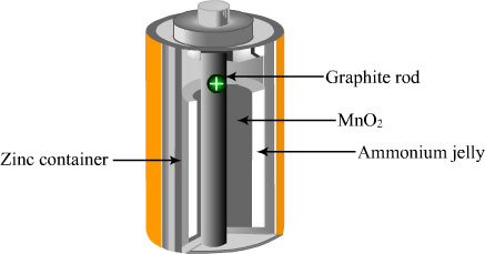
It appears to me that if one wants to make progress in mathematics, one should study the masters and not the pupils. - Niels Henrik Abel.
Nothing is better than reading and gaining more and more knowledge - Stephen William Hawking.
Offline
#519 2019-10-23 00:36:28
- Jai Ganesh
- Administrator
- Registered: 2005-06-28
- Posts: 53,626
Re: Miscellany
419) Tessellations
For centuries, mathematicians and artists alike have been fascinated by tessellations, also called tilings. Tessellations of a plane can be found in the regular patterns of tiles in a bathroom floor, or flagstones in a patio. They are also widely used in the design of fabric or wallpaper. Tessellations of three-dimensional space play an important role in chemistry, where they govern the shapes of crystals.
A tessellation of a plane (or of space) is any subdivision of the plane (or space) into regions or "cells" that border each other exactly, with no gaps in between. The cells are usually assumed to come in a limited number of shapes; in many tessellations, all the cells are identical. Tessellations allow an artist to translate a small motif into a pattern that covers an arbitrarily large area. For mathematicians, tessellations provide one of the simplest examples of symmetry.
In everyday language, the word "symmetric" normally refers to an object with dihedral or mirror symmetry. That is, a mirror can be placed exactly in the middle of the object and the reflection of the mirrored half is the same as the half not mirrored. Such is the case with the leftmost tessellation in the figure. If an imaginary mirror is placed along the axis, then every seed-shaped cell has an identical mirror image on the other side of the axis. Likewise, every diamond-shaped cell has an identical diamond-shaped mirror image.
Mirror symmetry is not the only kind of symmetry present in tessellations. Other kinds include translational symmetry, in which the entire pattern can be shifted; rotational symmetry, in which the pattern can be rotated about a central point; and glide symmetry, in which the pattern can first be reflected and then shifted (translated) along the axis of reflection. Examples of these three kinds of symmetry are shown in the other three blocks of the figure. In each case, the tessellation is called symmetric under a transformation only if that transformation moves every cell to an exactly matching cell.
The collection of all the transformations that leave a tessellation unchanged is called its symmetry group. This is the tool that mathematicians traditionally use to classify different types of tilings. The classification of patterns can be further refined according to whether the symmetry group contains translations in one dimension only (a frieze group), in two dimensions (a wallpaper group), or three dimensions (a crystallographic group). Within these categories, different groups can be distinguished by the number and kind of rotations, reflections, and glides that they contain. In total, there are seven different frieze groups, seventeen wallpaper groups, and 230 crystallographic groups.
To an artist, the design of a successful pattern involves more than mathematics. Nevertheless, the use of symmetry groups can open the artist's eyes to patterns that would have been hard to discover otherwise. A stunning variety of patterns with different kinds of symmetries can be found in the decorations of tiles at the Alhambra in Spain, built in the thirteenth and fourteenth centuries.
In modern times, the greatest explorer of tessellation art was M. C. Escher. This Dutch artist, who lived from 1898 to 1972, enlivened his woodcuts by turning the cells of the tessellations into whimsical human and animal figures. Playful as they appear, such images were based on a deep study of the seventeen (two-dimensional) wallpaper groups.
One of the most fundamental constraints on classical wallpaper patterns is that their rotational symmetries can only include half-turns, one-third turns, quarter-turns, or one-sixth turns. This constraint is related to the fact that regular triangles, squares, and hexagons fit together to cover the plane, whereas regular pentagons do not.
However, one of the most exciting developments of recent years has been the discovery of simple tessellations that do exhibit five-fold rotational symmetry. The most famous are the Penrose tilings, discovered by English mathematician Roger Penrose in 1974, which use only two shapes, called a "kite" and a "dart." Three-dimensional versions of Penrose tilings have been found in certain metallic alloys. These "non-periodic tilings," or "quasi crystals," are not traditional wallpaper or crystal patterns because they have no translational symmetries. That is, if the pattern is shifted in any direction and any distance, discrepancies between the original and the shifted patterns appear.
Nevertheless, Penrose tilings have a great deal of long-range structure to them, just as ordinary crystals do. For example, in any Penrose tiling the ratio of the number of kites to the number of darts equals the "golden ratio," 1.618…. Mathematicians are still looking for new ways to explain such patterns, as well as ways to construct new non-periodic tilings.

It appears to me that if one wants to make progress in mathematics, one should study the masters and not the pupils. - Niels Henrik Abel.
Nothing is better than reading and gaining more and more knowledge - Stephen William Hawking.
Offline
#520 2019-10-25 00:02:48
- Jai Ganesh
- Administrator
- Registered: 2005-06-28
- Posts: 53,626
Re: Miscellany
420) Tractor
Tractor, high-power, low-speed traction vehicle and power unit mechanically similar to an automobile or truck but designed for use off the road. The two main types are wheeled, which is the earliest form, and continuous track. Tractors are used in agriculture, construction, road building, etc., in the form of bulldozers, scrapers, and diggers. A notable feature of tractors in many applications is the power-takeoff accessory, used to operate stationary or drawn machinery and implements.
The first tractors, in the sense of powered traction vehicles, grew out of the stationary and portable steam engines operated on farms in the late 19th century and used to haul plows by the 1890s. In 1892 an Iowa blacksmith, John Froehlich, built the first farm vehicle powered by a gasoline engine. The first commercially successful manufacturers were C.W. Hart and C.H. Parr of Charles City, Iowa. By World War I the tractor was well established, and the U.S. Holt tractor was an inspiration for the tanks built for use in the war by the British and French.
Belt and power takeoffs, incorporated in tractors from the beginning, were standardized first in the rear-mounted, transmission-derived power takeoff and later in the independent, or live-power, takeoff, which permitted operation of implements at a constant speed regardless of the vehicular speed. Many modern tractors also have a hydraulic power-takeoff system operated by an oil pump, mounted either on the tractor or on a trailer.
Most modern tractors are powered by internal-combustion engines running on gasoline, kerosene (paraffin), LPG (liquefied petroleum gas), or diesel fuel. Power is transmitted through a propeller shaft to a gearbox having 8 or 10 speeds and through the differential gear to the two large rear-drive wheels. The engine may be from about 12 to 120 horsepower or more. Until 1932, when oversize pneumatic rubber tires with deep treads were introduced, all wheel-type farm tractors had steel tires with high, tapering lugs to engage the ground and provide traction.
Crawler, caterpillar, or tracklaying tractors run on two continuous tracks consisting of a number of plates or pads pivoted together and joined to form a pair of endless chains, each encircling two wheels on either side of the vehicle. These tractors provide better adhesion and lower ground pressure than the wheeled tractors do. Crawler tractors may be used on heavy, sticky soil or on very light soil that provides poor grip for a tire. The main chassis usually consists of a welded steel hull containing the engine and transmission. Tractors used on ground of irregular contours have tracks so mounted that their left and right front ends rise and fall independently of each other.
Four-wheel-drive tractors can be used under many soil conditions that immobilize two-wheel-drive tractors and caterpillars. Because of their complicated construction and consequent high cost, their use has grown rather slowly.
The single-axle (or walking) tractor is a small tractor carried on a pair of wheels fixed to a single-drive axle; the operator usually walks behind, gripping a pair of handles. The engine is usually in front of the axle, and the tools are on a bar behind. This type of machine may be used with a considerable range of equipment, including plows, hoes, cultivators, sprayers, mowers, and two-wheeled trailers. When the tractor is coupled to a trailer, the operator rides.

It appears to me that if one wants to make progress in mathematics, one should study the masters and not the pupils. - Niels Henrik Abel.
Nothing is better than reading and gaining more and more knowledge - Stephen William Hawking.
Offline
#521 2019-10-27 00:42:39
- Jai Ganesh
- Administrator
- Registered: 2005-06-28
- Posts: 53,626
Re: Miscellany
421) Thermometer
Thermometer, instrument for measuring the temperature of a system. Temperature measurement is important to a wide range of activities, including manufacturing, scientific research, and medical practice.
The accurate measurement of temperature developed relatively recently in human history. The invention of the thermometer is generally credited to the Italian mathematician-physicist Galileo Galilei (1564–1642). In his instrument, built about 1592, the changing temperature of an inverted glass vessel produced an expansion or contraction of the air within it, which in turn changed the level of the liquid with which the vessel’s long, openmouthed neck was partially filled. This general principle was perfected in succeeding years by experimenting with liquids such as mercury and by providing a scale to measure the expansion and contraction brought about in such liquids by rising and falling temperatures.
By the early 18th century as many as 35 different temperature scales had been devised. The German physicist Daniel Gabriel Fahrenheit in 1700–30 produced accurate mercury thermometers calibrated to a standard scale that ranged from 32°, the melting point of ice, to 96° for body temperature. The unit of temperature (degree) on the Fahrenheit temperature scale is 1/180 of the difference between the boiling (212°) and freezing points of water. The first centigrade scale (made up of 100 degrees) is attributed to the Swedish astronomer Anders Celsius, who developed it in 1742. Celsius used 0° for the boiling point of water and 100° for the melting point of snow. This was later inverted to put 0° on the cold end and 100° on the hot end, and in that form it gained widespread use. It was known simply as the centigrade scale until in 1948 the name was changed to the Celsius temperature scale. In 1848 the British physicist William Thomson (later Lord Kelvin) proposed a system that used the degree Celsius but was keyed to absolute zero (−273.15 °C); the unit of this scale is now known as the kelvin. The Rankine scale employs the Fahrenheit degree keyed to absolute zero (−459.67 °F).
Any substance that somehow changes with alterations in its temperature can be used as the basic component in a thermometer. Gas thermometers work best at very low temperatures. Liquid thermometers are the most common type in use. They are simple, inexpensive, long-lasting, and able to measure a wide temperature span. The liquid is almost always mercury, sealed in a glass tube with nitrogen gas making up the rest of the volume of the tube.
Electrical-resistance thermometers characteristically use platinum and operate on the principle that electrical resistance varies with changes in temperature. Thermocouples are among the most widely used industrial thermometers. They are composed of two wires made of different materials joined together at one end and connected to a voltage-measuring device at the other. A temperature difference between the two ends creates a voltage that can be measured and translated into a measure of the temperature of the junction end. The bimetallic strip constitutes one of the most trouble-free and durable thermometers. It is simply two strips of different metals bonded together and held at one end. When heated, the two strips expand at different rates, resulting in a bending effect that is used to measure the temperature change.
Other thermometers operate by sensing sound waves or magnetic conditions associated with temperature changes. Magnetic thermometers increase in efficiency as temperature decreases, which makes them extremely useful in measuring very low temperatures with precision. Temperatures can also be mapped, using a technique called thermography that provides a graphic or visual representation of the temperature conditions on the surface of an object or land area.

It appears to me that if one wants to make progress in mathematics, one should study the masters and not the pupils. - Niels Henrik Abel.
Nothing is better than reading and gaining more and more knowledge - Stephen William Hawking.
Offline
#522 2019-10-29 00:42:19
- Jai Ganesh
- Administrator
- Registered: 2005-06-28
- Posts: 53,626
Re: Miscellany
422) Contact lens
Contact lens, thin artificial lens worn on the surface of the eye to correct refractive defects of vision. The first contact lens, made of glass, was developed by Adolf Fick in 1887 to correct irregular astigmatism. The early lenses, however, were uncomfortable and could not be worn for long. Until the development of optical instruments that could measure the curvature of the cornea (the transparent surface of the eye that covers the iris and the pupil), the contact lens was made by taking an impression of the eye and fashioning a lens on a mold.
Contact lenses most effectively neutralize visual defects arising from irregular curvatures of the cornea. They are the preferred treatment for some varieties of astigmatism and aphakia (absence of the eye’s crystalline lens). They also can be functionally and cosmetically appealing substitutes for eyeglasses to treat myopia (nearsightedness) and other visual defects.
In the mid-1900s, plastic-based contact lenses were designed that rested on a cushion of tears on the cornea, covering the area over the iris and pupil. These older hard-plastic contact lenses had a limited wearing time because of potential irritation of the cornea, and they required a period of adaptation when first worn. Both front and back surfaces of the hard contact lens are spherically curved, altering refractive properties by changing the shape of the tear film on the eye’s surface, which conforms to the curve of the rear surface of the contact lens, and by a difference in curvature between the two surfaces of the lens itself. In the 1970s, gas-permeable rigid contact lenses were developed that allowed much more oxygen to pass through to the corneal surface, thus increasing comfort and wear time.
Also in the 1970s, larger “soft” lenses, made from a water-absorbing plastic gel for greater flexibility, were introduced. Soft contact lenses are usually comfortable because they allow oxygen to penetrate to the eye’s surface. Their large size makes them more difficult to lose than hard lenses. Their delicacy, however, makes them more subject to damage, and, as with all contact lenses, they require careful maintenance. They are less effective than hard lenses in treating astigmatism, because they reflect the underlying corneal curvature more closely. In 2005 hybrid lenses were developed that are gas-permeable and rigid and surrounded by a soft ring. These lenses provide the comfort of a soft lens with the visual sharpness of a hard lens.
Contact lenses have particular advantages in treating certain defects that can be corrected only partially by prescription eyeglasses; for example, contact lenses avoid the distortion of size that occurs with thick corrective lenses. However, most contact lenses cannot be worn overnight, as this significantly increases the risk of serious corneal infections.
Contact lenses can also be used in certain situations to protect the corneal surface during healing and to relieve discomfort derived from corneal surface problems.

It appears to me that if one wants to make progress in mathematics, one should study the masters and not the pupils. - Niels Henrik Abel.
Nothing is better than reading and gaining more and more knowledge - Stephen William Hawking.
Offline
#523 2019-10-31 00:05:58
- Jai Ganesh
- Administrator
- Registered: 2005-06-28
- Posts: 53,626
Re: Miscellany
423) Dredging and Dredgers
Dredging is a displacement of soil, carried out under water. It serves several different purposes. One of the applications meets the need to maintain minimum depths in canals and harbours by removing mud, sludge, gravel and rocks. Maintenance dredging is now only a basic task, while other fields are growing in demand much faster: creating new land for port and industrial development; trenching, backfilling and protection work for offshore pipelines, coastal outfall pipelines and for cables laid on the sea bed; environmental dredging and clean-up of contaminated sediments; replenishment of beaches and coastlines, not only for coastal protection, but also for recreational uses.
There are two methods of dredging: mechanical excavating and hydraulic excavating. Mechanical excavating is applied to cohesive soils. The dredged material is excavated and removed using mechanical means such as grabs, buckets, cutter heads or scoops. Hydraulic excavating is done with special water jests in cohesionless soils such as silt, sand and gravel. The dredged material which has been loosened from the sea-bed is sucked up and transported further as a mixture (solid material and water) using centrifugal pumps.
Mechanical dredgers
- Backhoe dredger – A backhoe dredger is based on the giant land-based backhoe excavator that is mounted at one end of a spud-rigged pontoon. Its main advantage is its ability to dredge a wide range of materials, including debris and soft, weathered or fractured rocks.
- Bucket chain dredger – Bucket chain dredge or bucket ladder dredge is a stationary dredger equipped with an endless chain of buckets carried by the ladder. The buckets are attached to a chain and graded according to size (200 to 1000 litres). Bucket dredgers are held in place by anchors. These days, this classic vessel is mainly used on environmental dredging projects.
The bucket chain dredger uses a continuous chain of buckets to scoop material from the bottom and raise it above water. The buckets are inverted as they pass over the top tumbler, causing their contents to be discharged by gravity onto chutes which convey the spoil into barges alongside. Positioning and movements are achieved by means of winches and anchors.
- Cutter suction dredger – The cutter suction dredger is a stationary dredger equipped with a cutter head, which excavates the soil before it is sucked up by the flow of the dredge pump. During operation the cutter suction dredger moves around a spud pole by pulling and slacking on the two fore sideline wires. These dredgers are often used to dredge trenches for pipe lines and approach channels in hard soil. Seagoing cutter suction dredgers have their own propulsion..
- Grab dredger – A grab dredger employs a grab mounted on cranes or crane beams. Dredged material is loaded into barges that operate independently. Grabs can manage both sludge and hard objects (blocks of stone, wrecks) and this makes them suitable for clearing up waters that are difficult to access (canals in cities), or for gravel winning and maintenance dredging on uneven beds.
Suction dredgers
- Plain suction dredger – A plain suction dredger is a stationary dredger positioned on wires with at least one dredge pump connected to the suction pipe situated in a well in front of a pontoon. The dredged soil is discharged either by pipeline or by barges.
- Trailing suction hopper dredger (TSHD) – The trailing suction hopper dredger is nonstationary dredger, which means that it is not anchored by wires or spud but it is dynamically positioned; the dredger uses its propulsion equipment to proceed over the track. It is a shipshaped vessel with hopper type cargo holds to store the slurry. At each side of the ship is a suction arm, which consists of a lower and a higher part, connected through cardanic joints. Trailing suction hopper dredgers are used for maintenance work (removal of deposits in approach channels) and dredging of trenches in softer soils.
TSHD has several special features, the main one being a drag arm which works as vacuum cleaner. Drag arm consists of a suction bend, lower and upper suction pipes connected via double cardan hinge and a draghead.
The suction bend is mounted in a trunnion which forms part of the sliding piece; as the pipe goes outboard the sliding piece enters the guide on the hull and is lowered until the bend is in line with the suction inlet below the waterline.
The suction pipe can be equipped with an integral submerged dredge pump. Submerged dredge pumps have become more and more popular with operators of larger trailing suction hopper dredges. Locating the dredge pump in the suction pipe positions is much closer to the seabed than a conventional dredge pump housed in the hull.
The drag arm is hoisted outboard and lowered to dredging depth with the aid of gantries. When not in use, it is lifted above the main deck level and pulled inboard with the hydraulically powered gantries for storage.
Discharge operations, discharge installations
When the vessel has to be discharged, jet pumps are used in the hopper to dilute the spoil so that it can be pumped ashore or discharged o the seabed through bottom doors. Occasionally, accurate placement of the material at great depths is possible via the suction pipes.
Fixed means of transporting dredged soil requires a floating pipeline from ship to shore, a powerful pump and a special link between pipeline and vessel – the bow coupling. Fixed and flexible models are in use. Fixed bow coupling has one degree of freedom (pitch), the flexible one has two degrees of freedom (pitch and turn). The flexible bow coupling can handle difficult sea conditions and reduces loads on the floating pipeline.
The mixture can also be jetted forward over the ship bow via a mixture jetting nozzle (rainbowing).
It appears to me that if one wants to make progress in mathematics, one should study the masters and not the pupils. - Niels Henrik Abel.
Nothing is better than reading and gaining more and more knowledge - Stephen William Hawking.
Offline
#524 2019-11-02 00:32:59
- Jai Ganesh
- Administrator
- Registered: 2005-06-28
- Posts: 53,626
Re: Miscellany
424) Fertilizer
Fertilizer, natural or artificial substance containing the chemical elements that improve growth and productiveness of plants. Fertilizers enhance the natural fertility of the soil or replace the chemical elements taken from the soil by previous crops.
The use of manure and composts as fertilizers is probably almost as old as agriculture. Modern chemical fertilizers include one or more of the three elements that are most important in plant nutrition: nitrogen, phosphorus, and potassium. Of secondary importance are the elements sulfur, magnesium, and calcium.
Most nitrogen fertilizers are obtained from synthetic ammonia; this chemical compound (NH3) is used either as a gas or in a water solution, or it is converted into salts such as ammonium sulfate, ammonium nitrate, and ammonium phosphate, but packinghouse wastes, treated garbage, sewage, and manure are also common sources of it. Phosphorus fertilizers include calcium phosphate derived from phosphate rock or bones. The more soluble superphosphate and triple superphosphate preparations are obtained by the treatment of calcium phosphate with sulfuric and phosphoric acid, respectively. Potassium fertilizers, namely potassium chloride and potassium sulfate, are mined from potash deposits. Mixed fertilizers contain more than one of the three major nutrients—nitrogen, phosphorus, and potassium. Mixed fertilizers can be formulated in hundreds of ways.
On modern farms a variety of machines are used to apply synthetic fertilizer in solid, gaseous, or liquid form. One type distributes anhydrous ammonia, a liquid under pressure, which becomes a nitrogenous gas when freed from pressure as it enters the soil. A metering device operates valves to release the liquid from the tank. Solid-fertilizer distributors have a wide hopper, with holes in the bottom; distribution is effected by various means, such as rollers, agitators, or endless chains traversing the hopper bottom. Broadcast distributors have a tub-shaped hopper from which the material falls onto revolving disks that distribute it in a broad swath.
Manure, organic material that is used to fertilize land, usually consisting of the feces and urine of domestic livestock, with or without accompanying litter such as straw, hay, or bedding. Farm animals void most of the nitrogen, phosphorus, and potassium that is present in the food they eat, and this constitutes an enormous fertility resource. In some countries, human excrement is also used. Livestock manure is less rich in nitrogen, phosphorus, and potash than syntheticfertilizers and hence must be applied in much greater quantities than the latter. A ton of manure from cattle, hogs, or horses usually contains only 10 pounds of nitrogen, 5 pounds of phosphorus pentoxide, and 10 pounds of potash. But manure is rich in organic matter, or humus, and thus improves the soil’s capacity to absorb and store water, thus preventing erosion. Much of the potassium and nitrogen in manure can be lost through leaching if the material is exposed to rainfall before being applied to the field. These nutrient losses may be prevented by such methods as stacking manure under cover or in pits to prevent leaching, spreading it on fields as soon as it is feasible, and spreading preservative materials in the stable. A green manure is a cover crop of some kind, such as rye, that is plowed under while still green to add fertility and conditioning to the soil.
The use of manure as fertilizer dates to the beginnings of agriculture. On modern farms manure is usually applied with a manure spreader, a four-wheeled self-propelled or two-wheeled tractor-drawn wagon. As the spreader moves, a drag-chain conveyor located at the bottom of the box sweeps the manure to the rear, where it is successively shredded by a pair of beaters before being spread by rotating spiral fins. Home gardeners like to use well-rotted manure, since it is less odorous, more easily spread, and less likely to “burn” plants.

It appears to me that if one wants to make progress in mathematics, one should study the masters and not the pupils. - Niels Henrik Abel.
Nothing is better than reading and gaining more and more knowledge - Stephen William Hawking.
Offline
#525 2019-11-04 00:29:51
- Jai Ganesh
- Administrator
- Registered: 2005-06-28
- Posts: 53,626
Re: Miscellany
425) Copper
Copper (Cu), chemical element, a reddish, extremely ductile metal of Group 11 (Ib) of the periodic table that is an unusually good conductor of electricity and heat. Copper is found in the free metallic state in nature. This native copper was first used (c. 8000 BCE) as a substitute for stone by Neolithic (New Stone Age) humans. Metallurgy dawned in Mesopotamia as copper was cast to shape in molds (c. 4000 BCE), was reduced to metal from ores with fire and charcoal, and was intentionally alloyed with tin as bronze (c. 3500 BCE). The Roman supply of copper came almost entirely from Cyprus. It was known as aes Cyprium, “metal of Cyprus,” shortened to cyprium and later corrupted to cuprum.
Occurrence, Uses, And Properties
Native copper is found at many locations as a primary mineral in basaltic lavas and also as reduced from copper compounds, such as sulfides, chlorides, and carbonates. Copper occurs combined in many minerals, such as chalcocite, chalcopyrite, bornite, cuprite, malachite, and azurite. It is present in the ashes of seaweeds, in many sea corals, in the human liver, and in many mollusks and arthropods. Copper plays the same role of oxygen transport in the hemocyanin of blue-blooded mollusks and crustaceans as iron does in the hemoglobin of red-blooded animals. The copper present in humans as a trace element helps catalyze hemoglobin formation. A porphyry copper deposit in the Andes Mountains of Chile is the greatest known deposit of the mineral. By the early 21st century Chile had become the world’s leading producer of copper. Other major producers include Peru, China, and the United States.
Copper is commercially produced mainly by smelting or leaching, usually followed by electrodeposition from sulfate solutions. The major portion of copper produced in the world is used by the electrical industries; most of the remainder is combined with other metals to form alloys. (It is also technologically important as an electroplated coating.) Important series of alloys in which copper is the chief constituent are brasses (copper and zinc), bronzes (copper and tin), and nickel silvers (copper, zinc, and nickel, no silver). There are many useful alloys of copper and nickel, including Monel; the two metals are completely miscible. Copper also forms an important series of alloys with aluminum, called aluminum bronzes. Beryllium copper (2 percent Be) is an unusual copper alloy in that it can be hardened by heat treatment. Copper is a part of many coinage metals. Long after the Bronze Age passed into the Iron Age, copper remained the metal second in use and importance to iron. By the 1960s, however, cheaper and much more plentiful aluminum had moved into second place in world production.
Copper is one of the most ductile metals, not especially strong or hard. Strength and hardness are appreciably increased by cold-working because of the formation of elongated crystals of the same face-centred cubic structure that is present in the softer annealed copper. Common gases, such as oxygen, nitrogen, carbon dioxide, and sulfur dioxide are soluble in molten copper and greatly affect the mechanical and electrical properties of the solidified metal. The pure metal is second only to silver in thermal and electrical conductivity. Natural copper is a mixture of two stable isotopes: copper-63 (69.15 percent) and copper-65 (30.85 percent).
Because copper lies below hydrogen in the electromotive series, it is not soluble in acids with the evolution of hydrogen, though it will react with oxidizing acids, such as nitric and hot, concentrated sulfuric acid. Copper resists the action of the atmosphere and seawater. Exposure for long periods to air, however, results in the formation of a thin green protective coating (patina) that is a mixture of hydroxocarbonate, hydroxosulfate, and small amounts of other compounds. Copper is a moderately noble metal, being unaffected by nonoxidizing or noncomplexing dilute acids in the absence of air. It will, however, dissolve readily in nitric acid and in sulfuric acid in the presence of oxygen. It is also soluble in aqueous ammonia or KCN in the presence of oxygen because of the formation of very stable cyano complexes upon dissolution. The metal will react at red heat with oxygen to give cupric oxide, CuO, and, at higher temperatures, cuprous oxide, Cu2O. It reacts on heating with sulfur to give cuprous sulfide, Cu2S.
Principal Compounds
Copper forms compounds in the oxidation states +1 and +2 in its normal chemistry, although under special circumstances some compounds of trivalent copper can be prepared. It has been shown that trivalent copper survives no more than a few seconds in an aqueous solution.
Copper(I) (cuprous) compounds are all diamagnetic and, with few exceptions, colourless. Among the important industrial compounds of copper(I) are cuprous oxide (Cu2O), cuprous chloride (Cu2Cl2), and cuprous sulfide (Cu2S). Cuprous oxide is a red or reddish brown crystal or powder that occurs in nature as the mineral cuprite. It is produced on a large scale by reduction of mixed copper oxide ores with copper metal or by electrolysis of an aqueous solution of sodium chloride using copper electrodes. The pure compound is insoluble in water but soluble in hydrochloric acid or ammonia. Cuprous oxide is used principally as a red pigment for antifouling paints, glasses, porcelain glazes, and ceramics and as a seed or crop fungicide.
Cuprous chloride is a whitish to grayish solid that occurs as the mineral nantokite. It is usually prepared by reduction of copper(II) chloride with metallic copper. The pure compound is stable in dry air. Moist air converts it to a greenish oxygenated compound, and upon exposure to light it is transformed into copper(II) chloride. It is insoluble in water but dissolves in concentrated hydrochloric acid or in ammonia because of the formation of complex ions. Cuprous chloride is used as a catalyst in a number of organic reactions, notably the synthesis of acrylonitrile from acetylene and HCN; as a decolourizing and desulfurizing agent for petroleum products; as a denitrating agent for cellulose; and as a condensing agent for soaps, fats, and oils.
Cuprous sulfide occurs in the form of black powder or lumps and is found as the mineral chalcocite. Large quantities of the compound are obtained by heating cupric sulfide (CuS) in a stream of hydrogen. Cuprous sulfide is insoluble in water but soluble in ammonium hydroxide and nitric acid. Its applications include use in solar cells, luminous paints, electrodes, and certain varieties of solid lubricants.
Copper(II) compounds of commercial value include cupric oxide (CuO), cupric chloride (CuCl2), and cupric sulfate (CuSO4). Cupric oxide is a black powder that occurs as the minerals tenorite and paramelaconite. Large amounts are produced by roasting mixed copper oxide ores in a furnace at a temperature below 1,030 °C (1,900 °F). The pure compound can be dissolved in acids and alkali cyanides. Cupric oxide is employed as a pigment (blue to green) for glasses, porcelain glazes, and artificial gems. It is also used as a desulfurizing agent for petroleum gases and as an oxidation catalyst.
Cupric chloride is a yellowish to brown powder that readily absorbs moisture from the air and turns into the greenish blue hydrate, CuCl2∙2H2O. The hydrate is commonly prepared by passing chlorine and water in a contacting tower packed with metallic copper. The anhydrous salt is obtained by heating the hydrate to 100 °C (212 °F). Like cuprous chloride, cupric chloride is used as a catalyst in a number of organic reactions—e.g., in chlorination of hydrocarbons. In addition, it serves as a wood preservative, mordant (fixative) in the dyeing and printing of fabrics, disinfectant, feed additive, and pigment for glass and ceramics.
Cupric sulfate is a salt formed by treating cupric oxide with sulfuric acid. It forms as large, bright blue crystals containing five molecules of water (CuSO4∙5H2O) and is known in commerce as blue vitriol. The anhydrous salt is produced by heating the hydrate to 150 °C (300 °F). Cupric sulfate is utilized chiefly for agricultural purposes, as a pesticide, germicide, feed additive, and soil additive. Among its minor uses are as a raw material in the preparation of other copper compounds, as a reagent in analytic chemistry, as an electrolyte for batteries and electroplating baths, and in medicine as a locally applied fungicide, bactericide, and astringent.
Other important copper(II) compounds include cupric carbonate, Cu2(OH)2CO3, which is prepared by adding sodium carbonate to a solution of copper sulfate and then filtering and drying the product. It is used as a colouring agent.
It appears to me that if one wants to make progress in mathematics, one should study the masters and not the pupils. - Niels Henrik Abel.
Nothing is better than reading and gaining more and more knowledge - Stephen William Hawking.
Offline